
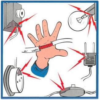
Every person is interested in the issue of security in his own home. Especially when it comes to ordinary electrical appliances. A small breakdown or short circuit is enough for them to turn into deadly objects.
Particularly dangerous in the home are appliances such as boilers and washing machine. The fact is that they are constantly in contact with water. And it is known to transmit electric current best. In the worst case scenario, you won't even need to touch the body, just step into a puddle of water.
The consequences of an electric shock are more than serious, including cardiac arrest. That is why you need to do everything possible to ensure that every household appliance in the house is safe. Now there are two main methods of protection: grounding and grounding. How they differ from each other, and in which cases it is worth using the first method, and in which the second, we will look into below.
Means of protection
In some cases, traffic jams and other protective devices do not operate when a malfunction occurs. The result of this is a violation of insulation. As a result, the metal elements of the body become excellent conductors, carrying a huge danger.
Fortunately, there is grounding and grounding. Both methods allow you to protect the human body from electrical damage. However, the technical implementation of these protection methods electrical appliances seriously different.
Some parts of electrical appliances, due to the installation features, are live. In this case, manufacturers use special casings. Other protective measures, such as barriers and mesh barriers, are also possible. Nevertheless, it will not be possible to do without grounding and grounding. They represent the extreme limit of protection, and to understand where to apply what, you need to know how they differ.
Grounding
To understand the difference between grounding and grounding, let's start with the first. This electrical protection system establishes a circuit between the appliance and ground. The result of such a scheme is more than effective - the voltage from the metal elements goes into the ground if the insulation accidentally breaks. You can completely calmly touch the equipment without fear of harming yourself.
Important ! The main difference between grounding and grounding, which is very similar to hearing, is that it works in networks where the neutral is isolated.
After you do the grounding. The current will flow through the conductor into the ground without creating any danger to humans. This, in fact, is what distinguishes this method of protection against grounding.
The grounding part must have a minimum resistance value. This is necessary so that the current enters the ground without any obstacles. This is another important factor that makes grounding different.
Grounding also differs from grounding in that it significantly increases the emergency current that is supplied when a short circuit occurs. The resistance indicator has a small value because otherwise in an emergency the voltage will be too low to activate protective circuit. Therefore, the device may remain live.

There are two main elements in grounding - the ground electrode and the conductor. Together they form a new device. This unit connects household appliances to the ground, making them safe for use. The operating principle of zeroing is significantly different. Therefore, the nulling scheme is used in new networks.
In the process of developing means of protection against spontaneous electric shocks, grounding was divided into two types: for removing pulsed current and for protection against thunderstorms. The unique design allows you to achieve two goals depending on the changes in some design elements.
In the first case, conductors maintain the normal operation of household appliances even in emergency situations. In the second, they prevent possible damage to living organisms. A similar situation arises in cases where the insulation of the phase wire is damaged. Since it comes out on a metal body, the consequences are more than serious.
Few people know, but grounding can also be natural, in other words, natural. Metal structures and pipelines, under certain conditions, can serve as excellent grounding.
Important ! It is prohibited to use pipes through which gas or other flammable substances are transported as natural grounding.
Classification
As mentioned above, in the process of constant development of technology, scientists have identified many unique grounding schemes. As a result, there are the following subgroups:
- TN-C
- TN-C-S,
They use different connection schemes; moreover, the number of conductors differs significantly. The abbreviation itself can tell a lot about the device. The first letter indicates the power source.
- T is the neutral leading to ground.
- I - completely insulated conductors.
The second letter indicates the method of grounding conductive parts.
- N - direct connection to the point.
- T - connection to the ground.
In the two diagrams above, you can see a few more letters separated by a line. The letter C indicates that there is only one conductor. S is about the diametrically opposite.
Zeroing
Now let's look at what grounding is and how it differs from conventional grounding. If we talk about a purely structural component, then this impact protection system electric current is a combination metal parts.
Each of the structural elements has zero stress. An option is also possible using a neutral. But it must have a three-phase source. The second option includes a grounded generator terminal. Moreover, the latter must have one phase.
Zeroing works as follows. As soon as the insulation is broken, a short circuit occurs. As a result, the circuit breaker trips. Of course, a lot depends on the system itself. For example, in some the fuses simply blow. In any case, the effect is the safety of people touching the devices.
Typically, grounding is used in equipment in which the neutral is tightly grounded. In principle, this system differs from grounding in this way. The peculiarity of the grounding circuit is that when the RCD is connected, the entire system is triggered. A similar incident occurs due to the difference in current strength.
Grounding also differs from grounding in that when installing an RCD and circuit breaker V non-standard situation these two elements can work. It is also possible to use a third device with higher performance.
Features of zeroing
Grounding differs from grounding in that during a short circuit, the current must necessarily reach the point at which the fuse will melt. Of course, there is another alternative in the form of a switch.
Important ! If the breaker does not trip or the fuses do not melt, electrical voltage there will be all the device housings connected to the protective circuit.
To prevent this from happening, you always need to monitor the neutral wire. The security of the entire system depends on its condition. In order to prevent current from flowing to all grounding objects, it is necessary to refrain from interrupting the neutral wire with any switches or fuses. By the way, this requirement is no different for grounding.
Key Differences
We have looked at the main characteristics of grounding and zeroing, now let's summarize how they differ from each other:
- Grounding is more efficient.
- Grounding is different in that it ensures safety by reducing current power.
- Zeroing differs in that the protection of electrical appliances is carried out by disconnecting the damaged area.
- Zeroing is difficult to install. Anyone can install grounding.
As you can see, the differences between grounding and grounding are quite significant.
Results
Grounding and grounding are two fundamentally different systems of protection against electric shock. Separately, it should be noted that the first system is used in houses with new wiring, and the second in old buildings.
If we talk about the advantages, then grounding is considered much more in a reliable way protection. But installing just such a scheme is not possible in all electrical networks.
One of effective means protection against electric shock are protective grounding and grounding of electrical installations. In accordance with GOST 12.1.009–76:
protective grounding – this is an intentional electrical connection to the ground or its earthvivalent of metal non-current-carrying parts that may be live;
zeroing – this is an intentional electrical connection withzero protective conductor of metal non-current-carrying conductorsparts that may be live.
In matters of application and practical implementation protective grounding and grounding should be guided by the requirements not only of the PUE, but also of GOST R 50571. GOST R 50571.2–94 “Electrical installations of buildings. Part 3. Main characteristics" provides a classification of grounding systems for electrical networks: IT, TT, TN-C, TN-C-S, TN-S (Fig. 2).
In relation to networks alternating current voltage up to 1 kV the designations have the following meaning.
First letter – nature of grounding of the power source (neutral mode of the secondary winding of the transformer):
I– isolated neutral;
T– solidly grounded neutral.
Second letter – nature of grounding of open conductive parts (metal casings) of the electrical installation:
T– direct connection of open conductive parts (OCP) with the ground (protective grounding);
N– direct connection of the frequency converter with the grounded neutral of the power source (grounding).
Subsequent letters (if any) – arrangement of zero working and zero protective conductors:
WITH– zero working (N) and zero protective (PE) conductors are combined throughout the network;
C– S– conductors N and PE are combined into parts of the network;
S– N and PE conductors operate separately throughout the entire network
Rice. 2. Types of grounding systems
Conductors used in various types networks must have certain designations and colors (Table 1).
Table 1
Conductor designation
|
Conductor name |
Designation |
Colors |
||
|
alphabetic |
graphic |
|||
|
Zero worker | ||||
|
Zero protective (protective) |
Yellow-green |
|||
|
Combined zero working and zero protective |
Yellow-green with blue marks at the ends applied during installation |
|||
|
in a three-phase network |
L 1, L 2, L 3 |
All colors except those listed above |
||
|
in a single-phase network | ||||
The scope of application of these protection methods is determined by the neutral mode and the voltage class of the electrical installation.
Protective grounding consists (Fig. 3) of a ground electrode 3 (metal conductors located in the ground with good contact with it) and a grounding conductor 2, connecting the metal casing of the electrical installation 1 with ground electrode.
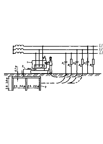
Rice. 3. Protective grounding diagram:
1 - Electrical installation; 2 - grounding conductor; 3 - ground electrode
The set of grounding conductor and grounding wires is called grounding device. Protective grounding is used in three-phase three-wire and single-phase two-wire AC networks with voltages up to 1000 V with an isolated neutral, as well as in networks with voltages above 1000 V AC and DC with any neutral mode.
Protective effect of the grounding device based on reducing to a safe value the current passing through a person at the moment of contact them of a damaged electrical installation.
When voltage enters the body of an electrical installation, a person, touching it and having good contact with the ground, closes himself electrical circuit: phase L1 - electrical installation housing 1 - man - earth - capacitive X L3 , X L2 and active R L 3 , R L 2 connection resistance of wires to ground, phases L3 andL2. A current will flow through the person. Despite the fact that the electrical wires of the network are installed on insulated supports, there is an electrical connection between them and the ground. It occurs due to imperfect insulation of wires, supports, etc. and the presence of capacitance between the wires and the ground. With a long distance of wires, this connection becomes significant, and its active R and capacitive X resistance decreases and becomes commensurate with the resistance of the human body. That is why, despite the absence of a visible connection, a person who is energized and in contact with the ground completes an electrical circuit between the different phases of the network.
In the presence of a grounding device, an additional circuit is formed: phase L1- electrical installation housing - grounding device - ground - resistance X L3 , R L3 , X L2 , R L2 - phases L3 And L2. As a result, the fault current is distributed between the grounding device and the person. Since the grounding resistance (it should be no more than 10 Ohms) is many times less human resistance (1000 Ohm), then a small current will pass through the human body without causing damage. The main part of the current will flow through the circuit through the ground electrode.
Grounding switches can be natural or artificial. As natural ground electrodes use metal structures and fittings of buildings and structures that have a good connection to the ground, water supply, sewer and other pipelines laid in the ground (with the exception of pipelines of flammable liquids, flammable and explosive gases and pipelines coated with insulation for protection against corrosion).
As artificial Grounding electrodes use single or grouped metal electrodes driven vertically or laid horizontally into the ground. Electrodes are made from sections of metal pipes with a diameter of at least 32 mm and a wall thickness of at least 3.5 mm, angle steel with a flange thickness of at least 4 mm, strips with a cross-section of at least 100 mm 2, as well as from sections of channels, bar steel with a diameter of at least 10 mm . Electrodes made of thinner profiles quickly fail due to corrosion. In addition, thin profiles have little contact with the ground, so their use is undesirable. The length of the electrodes and the distance between them is taken to be at least 2.5–3.0 m.
The vertical electrodes in the group grounding system are connected to each other by welding with a jumper made of similar materials and the same sections as the electrodes themselves. The grounding device must have an outlet to the outside (to the surface of the earth), welded from the same materials. It serves to connect the grounding conductor.
To perform grounding functionsgrounding device resistance in electrical installations with voltage up to 1000 Vonline with isolated neutral should be no more than 4 ohms.
The required resistance is achieved by installing the appropriate number of electrodes in the ground electrode, determined by calculation.
Grounding device resistance- this is the ratio of the voltage on the grounding device to the current flowing from the ground electrode into the ground. Distinguish remote And contour grounding devices.
Remote the device is located outside the site with grounded equipment. Its advantage is the ability to select soil with the lowest resistivity.
Contour Grounding is performed by driving electrodes along the contour of the grounded equipment and between it. This installation of electrodes creates an additional protective effect by increasing and leveling (more uniform distribution) of the earth potentials in the area where a person is located.
Zeroing - This is a deliberate electrical connection of metal non-current-carrying parts of electrical installations that may be energized with a solidly grounded neutral of a current source (generator or transformer).
In four-wire networks with a neutral wire and a solidly grounded neutral of a current source with a voltage of up to 1000 V, grounding is the main means of protection.
Connection of electrical installation housings to the neutral of the current source is carried out using zero protective conductor (RE- conductor). It should not be confused with zero worker wire (N - conductor), which is also connected to the source neutral, but serves to power single-phase electrical installations. The neutral protective conductor is laid along the route of the phase wires, in close proximity to them.
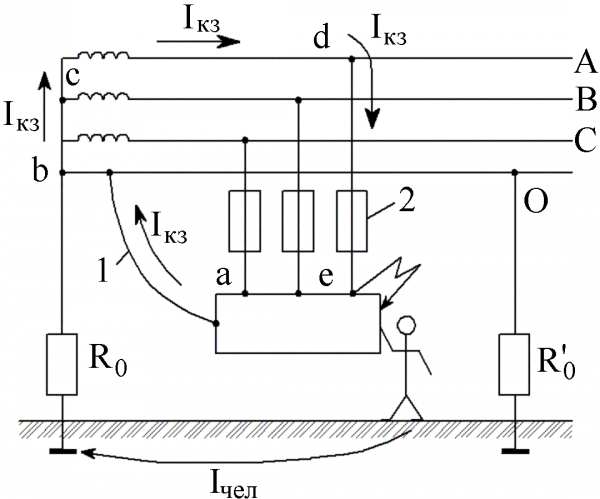
Protective effect of zeroing based to reduce to a safe value the current passing through a person at the moment of contact them damaged electrical installation, and subsequent disconnection of this installation from the network.
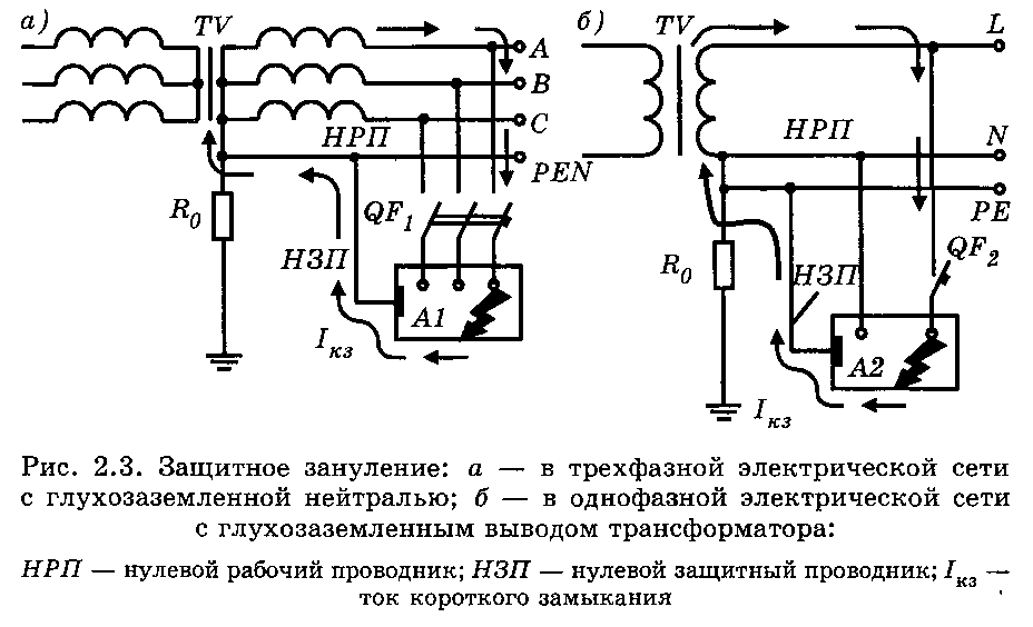
Zeroing works as follows: when voltage comes into contact with the body of a neutralized electrical installation 8 (Fig. 4) most of the current from it will go into the network through the neutral protective wire 6. By circuit: electrical installation housing 8 - man - earth - grounding device 9 - neutral working wire 5 - an insignificant current will flow that does not cause damage (due to the higher resistance of this circuit compared to the resistance of the circuit through the neutral protective wire 6). At the same time, a short circuit to the phase wire body with such a protection scheme automatically turns into a single-phase short circuit between the phase and neutral working wires 5 network, as a result in 0.2-7 s current protection is triggered(fuse blows 7, a circuit breaker is tripped, etc.), and the electrical installation, and with it the person, is completely de-energized.
Thus, at the initial moment, grounding works similarly to protective grounding, and subsequently it completely stops the effect of current on a person. Only in this case, the current passing through the human body before the protection is triggered will be several times less, because The resistance of the grounding conductor usually does not exceed 0.3 Ohm, and the resistance of the grounding conductor is allowed up to 4 Ohms.
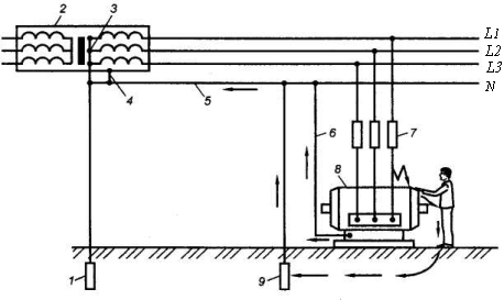
Rice. 4. Zeroing circuit:
1 - transformer neutral grounding conductor; 2 - current source (transformer); 3 - neutral of the current source; 4 - grounding of the transformer housing; 5 - zero working (also zero protective) wire of the network; 6 - neutral protective conductor of the electrical installation; 7 - fuse; 8 - electrical installation; 9 - re-grounding of the neutral protective wire of the network
In neutralized electrical installations up to 1 kV with a solidly grounded neutral, in order to reliably ensure automatic shutdown of the emergency section, the conductivity of the phase and neutral protective conductors and their connections must provide a short circuit current that is at least 3 times greater than the rated current of the fuse element of the nearest fuse or circuit breaker that has a release with an inverse current characteristic (thermal release), 1.4 times - for circuit breakers with electromagnetic releases with a rated current of up to 100 A and 1.25 times - with a current value of more than 100 A.
IN nullified in electrical installations up to 1 kV with a solidly grounded neutral (in order to reliably ensure automatic shutdown of the emergency section), the conductivity of phase and neutral protective conductors and their connections must ensure short circuit current.
Neutral protective conductor 5 network (Fig. 4) must ensure a reliable connection of electrical installation housings with the source neutral, therefore all connections are made by welding. It is prohibited to install fuses and switches in it (except for the case of simultaneous disconnection of phase wires).
Zero protective the wire 5 networks ground: at the current source using ground electrode 1; at the ends of overhead lines (or branches from them) longer than 200 m; as well as at overhead line inputs to electrical installations. Repeated groundings 9 are necessary to reduce the risk of electric shock when the neutral wire breaks and a phase is shorted to the electrical installation housing beyond the break point, as well as to reduce the voltage on the housing at the moment the current protection is triggered.
According to the PUEgrounding device resistance, to which the neutral of the current source is connected, taking into account natural and repeated grounding of the neutral wire there should be no more 2, 4 and 8 ohms respectively, at linear voltages of a three-phase current source 660, 380 and 220 V.
Total resistance spreading of grounding conductors (including natural ones) of all repeated grounding The PEN conductor of each overhead line at any time of the year must be no more than 5, 10 and 20 ohms respectively at linear voltages 660, 380 and 220 V three-phase power supply or380, 220 and 127 V single-phase current sources. Wherein grounding conductor spreading resistance each of the repeated groundings should be no more than 15, 30 and 60 ohms, respectively, at the same voltages.
With earth resistivity ρ O > 100 Ohm∙m it is allowed to increase the specified standards by 0.01 ρ O times, but not more than ten times.
Zeroing (grounding) of metal cases of portable electrical installations is carried out by the third conductor for single-phase or the fourth conductor for three-phase electrical receivers, located in the same shell with the phase wires.
The cores of these wires must be flexible, copper, their section must be equal to the cross-section of the phase conductors and be no less 1.5 mm 2 .
Plug-in connectors (plugs and sockets) must be made so that the connection of the grounding and neutral protective conductors occurs before the connection of the phase conductors, and the disconnection occurs in the reverse order. This is usually achieved by using a longer pin on the plug for the protective conductor than for the phase conductors. In all cases, the plug is connected to the electrical receiver, the socket to the network.
Individual protection meansfrom electric shock
Individual protection means from electric shock - electrical protective environmentsstva (EZS), which are divided into basic and additional.
Basic EZS- these are protective equipment, the insulation of which can withstand the operating voltage of electrical installations for a long time, which allows them to be used to touch live parts that are energized.
For work on electrical installations up to 1000 V These include: insulating rods, insulating and electrical clamps, dielectric gloves,plumbing and assembly tools with insulated handles, voltage indicators.
At electrical installation voltage over 1000 V fixed assets include insulating pantsgi, insulating and electrical clamps, pointers toyarn.
Additional EZS- these are protective equipment whose insulation cannot withstand the operating voltage of electrical installations for a long time. They are used to protect against touch and step voltages, and when working under voltage exclusively with the main electrical protection devices.
These include: under tension before 1000 V - dielectric galoshes, floor insulating matsrates; over 1000 V - dielectric gloves, boots, kovricks, insulating stands.EZS must be marked indicating the voltage for which they are designed, their insulating properties are subject to periodic testing within the time limits established by regulations.
Test periods for protective equipment against electric shock are presented in Table 2.
table 2
Time limits for testing protective equipment against electric shock (fragment)
|
Protective agent |
Electrical installation voltage |
Period of periodic testing, months. |
Period of periodic inspections, months. |
|
Insulating pliers | |||
|
Voltage indicators operating on the principle of active current flow |
before use |
||
|
Tools with insulated handles | |||
|
Rubber dielectric gloves | |||
|
Rubber dielectric galoshes | |||
|
Rubber dielectric mats |
Surely every novice electrician has heard about this method of protection against electric shock, such as grounding electrical appliances. Installation of a three-wire electrical network is a must during construction modern house. But what to do if you live in an old apartment in which such a protection system has not yet been used during construction? In this case, you need to do the so-called grounding of the electrical wiring. Read on to learn what both systems are and what the difference is between grounding and grounding!
Main differences
Both the first and second protection systems perform the same function - protecting a person from electric shock when touching a bare wire or electrical appliance on which it occurs. The only difference is that grounding provokes an instant power outage in the event of dangerous contact between a person and a wire, and grounding instantly removes dangerous voltage to the ground. This is their common difference from each other, in a nutshell.
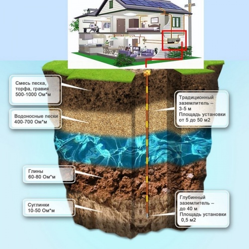
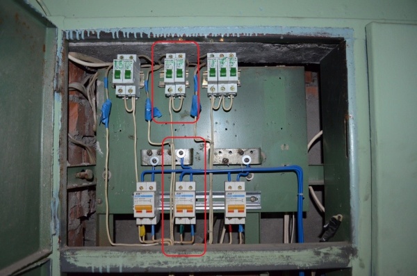
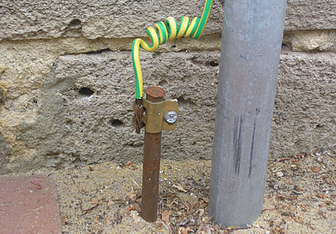
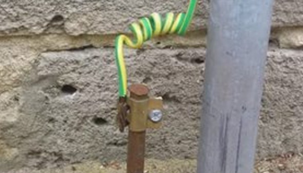
If we consider the issue in more detail, then we need to dwell on the operating principle of each protection option, based on which the difference between the alternative options will immediately be visible. Grounding works as follows: a grounding wire is connected to the housing of dangerous electrical appliances, which goes to the corresponding busbar in the distribution panel. From there, the common ground wire goes to the main ground loop - metal structure, dug into the ground next to the house (as shown in the photo). If a current breakdown occurs on the device body or contact with a bare current-carrying conductor, the danger will pass to a person.
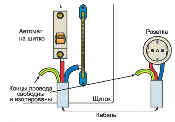
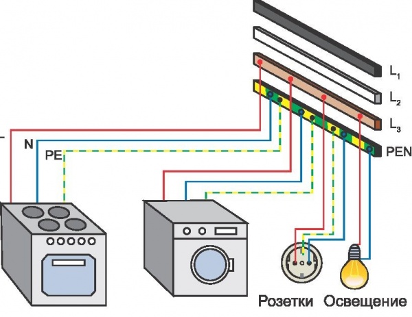
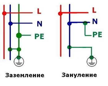
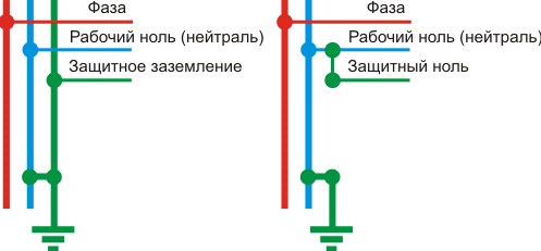
As for grounding, it represents the connection of the body of an electrical appliance with the neutral wire of the network - zero. The result is a closed loop, as shown in the diagram below. If a dangerous situation occurs, the circuit breakers on the input panel will immediately cut off the power.  You can clearly see the difference between grounding and grounding in this diagram:
We hope you now understand how the two differ. protective systems and, just as important, how they work. We also recommend that you look at the difference between them at visual video example:
Difference between alternatives
In this article you will find the differences between grounding and grounding. Probably every person has heard about such a method of protection as grounding electrical appliances. When building a modern house, installing a three-wire network is considered mandatory. Many may be wondering what to do if the apartment has old wiring.
In this case, you will need to ground the electrical wiring. In this article you will learn the difference between grounding and grounding.
Both systems are designed to perform the same functions. They protect people from electric shock. The difference is that grounding provokes an instant power outage in the event of dangerous human contact with the wire. Grounding will instantly drain the electrical current into the ground. You will need grounding for this. This is the difference between grounding and grounding.
If we consider this issue in more detail, then it is necessary to study what principle of operation each protection option has. Based on this, you can easily highlight the difference between alternative options. Grounding works as follows: a special wire is connected to the housing of electrical appliances, which leads to the corresponding bus. From there, the ground wire should go to the main ground loop, which is located next to the house. You can see the grounding loop in the photo below. If an electrical appliance fails in the house, then the danger can pass the person.
The grounding system is a connection between the housing of an electrical appliance and the neutral wire of the network. As a result, a closed loop is formed, as shown in the diagram below. may have a similar ground loop. If a dangerous situation occurs, a short circuit will occur, and the circuit breakers on the input panel will be able to turn off the power.
You can clearly see the difference between grounding and grounding in the diagram below:
We hope that you now understand the main differences between grounding and grounding. You can clearly see their difference in the video:
Which system is better?
In order for you to better understand all the main differences, we have brought to your attention the differences in using each system. Based on this material, you can draw your own conclusion.
- You can do the grounding at home with your own hands. To do this you only need welding machine. In order to create a grounding, certain knowledge may be required, which is associated with choosing the optimal point for connecting the wire to the neutral.
- If a wire breaks in the switchboard, then the grounding system will not work. As a result, you may become a victim of electric shock. This will not happen with a protective grounding system. If you perform routine inspection of all wires and connections, then this situation will not arise.
As you can see, making proper grounding in a private home is quite simple. This system will not only be durable, but also safe. To create a zero, you will need to call a wizard who will perform the installation yourself. You will also need to conduct regular inspections of your system. It is necessary to use zeroing only if you live in a Khrushchev building. We hope that now you understand the difference between grounding and grounding. Now you can see the differences between grounding and grounding in the video.
Grounding is a special connection of exposed metal parts of electrical equipment (electrical installations) to the neutral. This applies to metal non-current-carrying parts of equipment that are not (and should not be) energized in normal (operating) mode. The neutral to which the connection occurs must be solidly grounded.
In three-phase electrical networks, this is the neutral of a generator or power transformer; in a single-phase network, this is the solidly grounded terminal of the power source.
A neutral protective conductor (not to be confused with a neutral working conductor) is a conductor that connects metal grounded parts of electrical equipment with a solidly grounded neutral coming from a generator or supply power transformer.
The purpose of protective grounding is to ensure electrical safety in case of a short circuit to the metal casing of electrical equipment or electrical installation.
Zeroing principle
Protective grounding works as follows. If, when electrical power is applied, a phase hits (an accidental contact or breakdown of the insulation of a phase conductor) on a metal case with grounding, then a short circuit occurs, the value of the electric current sharply increases and the protection device (circuit breaker) is triggered or the fuse-link of the protective fuse blows, thereby de-energizing electrical equipment or electrical installation.
The resistance of the protective neutral conductor must be very low. This is necessary in order to ensure a short circuit current level sufficient for the protection to operate. Those. short-circuit current value must be sufficient for the protective device to operate.
If the electrical equipment is simply grounded, then, for example, in the event of a phase breakdown on the housing, the short circuit current may be insufficient for the circuit breaker to trip or the fuse link to blow.
Due to the fact that the neutral is grounded at the generator or transformer, the protective grounding ensures a sufficiently low touch voltage on the housing. Those. Protective grounding can be considered a kind of grounding.
Video - Grounding and grounding - what is the difference?
Protective grounding circuits
There are several schemes by which protective grounding is performed.
TN-C system
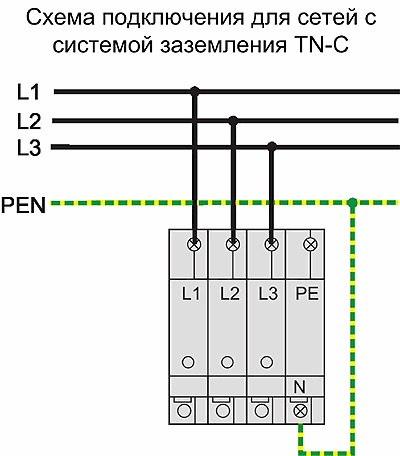
Enough simple system, along which protective grounding is performed. In it, the neutral conductor N and the protective conductor PE are combined along the entire length into one common conductor PEN. To implement protective grounding using the TN-C system, it is necessary to comply with very high requirements for the potential equalization system, as well as for the cross-sectional size of the combined PEN conductor.
Grounding according to the TN-C system is used in three-phase electrical networks, and in single-phase networks such nulling is strictly prohibited.
This system consists of connected N and PE conductors in part of the network, starting from the electrical power source. According to this system, electrical equipment in single-phase networks can be grounded.
Scope of application of protective grounding
Protective grounding is used in single-phase and three-phase networks AC up to 1 kV. The network must have a solidly grounded neutral.
Checking the effectiveness of protective grounding
The essence of protective grounding is that in the event of a short circuit of a phase to the body of electrical equipment, the damaged section of the circuit is automatically switched off. In order to check how effectively the protective grounding is performed, it is necessary to measure the resistance of the phase-zero loop at the point furthest from the power source. This will allow you to determine whether the protection device will work in the event of a single-phase short circuit. on the body.
The resistance of the phase-zero loop is measured using special measuring instruments. Devices for measuring the phase-zero loop have two probes. When measuring, one probe is connected to the active phase, and the second to the neutralized part of the electrical equipment.
As a result of the measurement, the resistance value of the phase-zero loop is determined. Knowing the value of the measured resistance and the value of the supply voltage, using the formula of Ohm's law for a section of the circuit, you can calculate the current of a single-phase short circuit, the calculated value of which must be greater than (or equal to) the operating current of the protective device.
Let's say that to protect the circuit from current overloads and short circuits, a circuit breaker is installed, the instantaneous operating current of which is 100A. The measured resistance value of the phase-zero loop is 2 Ohms, the phase voltage in the network is equal to the standard value of 220V.
We calculate the value of the single-phase short circuit current. According to Ohm's law, I = U/R = 220V/2Ohm = 110A.
Because rated short-circuit current is greater than the instantaneous operation (cut-off) current of the circuit breaker, then the protective grounding will be effective. If the calculated short-circuit current turned out to be less than the instantaneous operation current of the circuit breaker, then for the protective grounding to be effective, it would be necessary either to change the circuit breaker to a device with a lower operation current, or to look for a solution to reduce the resistance of the phase-zero loop.
Very often in calculations the operating current of the circuit breaker is multiplied by the so-called reliability coefficient Kn or safety factor. The fact is that the cutoff of the machine does not always correspond to the specified value, i.e. There may be some error, this is why the specified coefficient is introduced into the calculations. For older machines, Kn can be equal to, for example, 1.25 or 1.4. For new modern machines it can be equal to 1.1. This is due to the fact that new protection devices work more accurately.