
The directed movement of charged particles, which is called electric current, ensures a comfortable existence to modern man. Without it, production and construction facilities do not operate, medical devices in hospitals do not operate, there is no comfort in the home, and city and intercity transport is idle. But electricity is a servant of man only in case of complete control; if charged electrons can find another path, then the consequences will be disastrous. To prevent unpredictable situations, special measures are used, the main thing is to understand what the difference is. Grounding and grounding protect a person from electric shock.
The directional movement of electrons follows the path of least resistance. To avoid the passage of current through the human body, it is offered another direction with the least loss, which provides grounding or grounding. What is the difference between them remains to be seen.
Grounding
Grounding is a single conductor or a group made up of them in contact with the ground. With its help, the voltage supplied to the metal body of the units is reset along the path of zero resistance, i.e. to the ground.
Such electrical equipment in industry is also relevant for household appliances with steel external parts. A person touching the body of a refrigerator or washing machine that is energized will not cause electric shock. For this purpose, special sockets with a grounding contact are used.
Operating principle of RCD
For safe work industrial and household equipment is used, they use devices. Their work is based on comparing the incoming voltage through the phase wire electric current and leaving the apartment via the neutral conductor.
The normal operating mode of an electrical circuit shows the same current values in the named sections, the flows are directed in opposite directions. In order for them to continue to balance their actions, ensure balanced operation of the devices, they carry out the installation and installation of grounding and grounding.
A breakdown in any section of the insulation leads to the flow of current directed to the ground through the damaged area, bypassing the working neutral conductor. The RCD shows an imbalance of current, the device automatically turns off the contacts and the voltage disappears in the entire operating circuit.

For each individual operating condition, different settings are provided for turning off the RCD, usually the setting range is from 10 to 300 milliamps. The device operates quickly, the shutdown time is seconds.
Operation of the grounding device
To connect a grounding device to the housing of a household or industrial equipment A PE conductor is used, which is led out of the panel via a separate line with a special output. The design provides a connection between the housing and the ground, which is the purpose of grounding. The difference between grounding and grounding is that at the initial moment when connecting the plug to the socket, the working zero and phase are not switched in the equipment. The interaction disappears at the last minute when the contact opens. Thus, the chassis grounding has a reliable and permanent effect.
Two ways of grounding device
Protection and voltage removal systems are divided into:
- artificial:
- natural.
Artificial groundings are intended directly to protect equipment and people. Their installation requires horizontal and vertical steel metal longitudinal elements (pipes with a diameter of up to 5 cm or angles No. 40 or No. 60 with a length of 2.5 to 5 m are often used). This makes the difference between grounding and grounding. The difference is that a specialist is required to perform high-quality zeroing.
Natural grounding electrodes are used if they are located closest to an object or residential building. Pipelines in the ground made of metal serve as protection. It is impossible to use pipelines with flammable gases, liquids and those pipelines whose outer walls are treated with an anti-corrosion coating for protective purposes.

Natural objects not only serve to protect electrical appliances, but also fulfill their main purpose. The disadvantages of such a connection include access to pipelines for a fairly wide range of people from neighboring services and departments, which creates the risk of violating the integrity of the connection.
Zeroing
In addition to grounding, in some cases grounding is used; you need to distinguish what the difference is. Grounding and grounding remove voltage, they just do it different ways. The second method is the electrical connection of the housing, which is normally not energized, and the output of a single-phase electricity source, the neutral wire of a generator or transformer, the source direct current at its midpoint. When zeroed, the voltage from the housing is reset to a special distribution panel or transformer box.
Grounding is used in cases of unexpected voltage surges or breakdown of the insulation of the housing of industrial or household appliances. A short circuit occurs, leading to blown fuses and instantaneous automatic shutdown, this is the difference between grounding and neutralizing.
Zeroing principle
Variable three-phase circuits use the neutral conductor for various purposes. To ensure electrical safety, it is used to obtain the effect of a short circuit and voltage generated on the housing with phase potential in critical situations. In this case, a current appears that exceeds the rated value circuit breaker and contact ends.
Zeroing device
The difference between grounding and grounding can be seen in the connection example. The housing is connected with a separate wire to zero on the distribution panel. To do this, connect the third core of the electrical cable in the socket to the terminal provided for this in the socket. This method has the disadvantage that automatic shutdown requires a current greater than the specified settings. If in normal mode the disconnecting device ensures operation of the device with a current of 16 Amps, then small current breakdowns continue to flow without shutting down.
After this, it becomes clear what the difference is between grounding and neutralizing. Human body when exposed to a current of 50 milliamps, it may not be able to withstand and cardiac arrest will occur. Zeroing may not protect against such current indicators, since its function is to create loads sufficient to disconnect the contacts.
Grounding and zeroing, what is the difference?
There are differences between these two methods:
- when grounding, excess current and voltage generated on the housing are discharged directly into the ground, and when grounded, they are reset to zero in the panel;
- grounding is more effective ways in the matter of protecting people from electric shock;
- when using grounding, safety is achieved due to a sharp decrease in voltage, and the use of grounding ensures that the section of the line in which a breakdown occurred on the housing is switched off;
- When performing grounding, in order to correctly determine the zero points and choose a protection method, you will need the help of a specialist electrician, and any home craftsman can make grounding, assemble a circuit and deepen it into the ground.
Grounding is a system for removing voltage through a triangle located in the ground made of a metal profile welded at the joints. A properly designed circuit gives reliable protection, but all rules must be followed. Depending on the required effect, grounding and grounding of electrical installations are selected. The difference between grounding is that all elements of the device that are not under current in normal mode are connected to the neutral wire. Accidental contact of a phase with zeroed parts of the device leads to a sharp jump in current and shutdown of the equipment.
The resistance of the neutral neutral wire is in any case less than the same value of the circuit in the ground, therefore, when grounding, a short circuit occurs, which is, in principle, impossible when using an earth triangle. After comparing the operation of the two systems, it becomes clear what the difference is. Grounding and grounding differ in the method of protection, since there is a high probability of the neutral wire burning out over time, which must be constantly monitored. Zeroing is used very often in multi-storey buildings, since it is not always possible to arrange reliable and complete grounding.
Grounding does not depend on the phase phase of the devices, while the grounding device requires certain connection conditions. In most cases, the first method prevails in enterprises where safety requirements require increased safety. But even in everyday life, recently a circuit has often been installed to discharge the excess voltage that arises directly into the ground; this is a safer method.
Grounding protection directly concerns the electrical circuit; after an insulation breakdown, due to the flow of current into the ground, the voltage is significantly reduced, but the network continues to operate. When zeroed, a section of the line is completely switched off.
Grounding in most cases is used in lines with an arranged isolated neutral in IT and TT systems in three-phase networks with voltages up to 1 thousand volts or above this indicator for systems with a neutral in any mode. The use of grounding is recommended for lines with a solidly grounded neutral wire in networks TN-C-S, TN-C, TN-S with available N, PE, PEN conductors, this shows what the difference is. Grounding and grounding, despite their differences, are systems for protecting people and devices.
Useful Electrical Engineering Terms
To understand some of the principles by which protective grounding, grounding and disconnection are performed, you should know the definitions:
A solidly grounded neutral is a neutral wire from a generator or transformer, directly connected to the ground loop.
It can serve as an output from the source alternating current V single-phase network or the pole point of a direct current source in two-phase mains, as is the average output in three-phase direct voltage networks.
An insulated neutral is the neutral wire of a generator or transformer that is not connected to the ground loop or is in contact with it through a strong resistance field from alarm devices, protective devices, measuring relays and other devices.
Accepted designations of grounding devices in the network
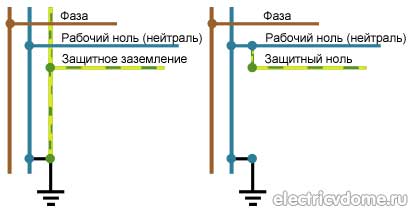
All electrical installations with grounding and neutral conductors present in them must be marked. Designations are applied to tires in the form letter designation PE with alternating transverse or longitudinal identical stripes of green or yellow color. Neutral neutral conductors are marked with the blue letter N, which indicates grounding and grounding. The description for the protective and working zero consists of putting down the letter designation PEN and painting it blue throughout its entire length with green-yellow tips.
Letter designations
The first letters in the explanation of the system indicate the selected nature of the grounding device:
- T - connection of the power source directly to ground;
- I - all live parts are isolated from the ground.
The second letter serves to describe the conductive parts regarding the connection to earth:
- T speaks about the mandatory grounding of all exposed live parts, regardless of the type of connection to the ground;
- N - means that protection of exposed parts under current is carried out through a solidly grounded neutral from the power source directly.
The letters separated by a dash from N indicate the nature of this connection and determine the method of arranging the neutral protective and working conductors:
- S - PE protection of the neutral and N-working conductors is made by separate wires;
- C - one wire is used for the protective and working zero.
Types of protective systems
The classification of systems is the main characteristic according to which protective grounding and grounding are arranged. General technical information is described in the third part of GOST R 50571.2-94. In accordance with it, grounding is carried out according to the IT, TN-C-S, TN-C, TN-S schemes.
The TN-C system was developed in Germany at the beginning of the 20th century. It provides for the combination of a working neutral wire and a PE conductor in one cable. The disadvantage is that when a zero burns out or another connection failure occurs, voltage appears on the equipment housings. Despite this, the system is used in some electrical installations until our time.

The TN-C-S and TN-S systems are designed to replace the unsuccessful TN-C grounding scheme. In the second protection scheme, two types of neutral wires were separated directly from the shield, and the circuit was a complex metal structure. This scheme turned out to be successful, since when the neutral wire was disconnected, no linear voltage appeared on the casing of the electrical installation.
The TN-C-S system differs in that the separation of the neutral wires is not carried out immediately from the transformer, but approximately in the middle of the line. This was not a good solution, since if a zero break occurs before the separation point, then the electric current on the housing will pose a threat to life.
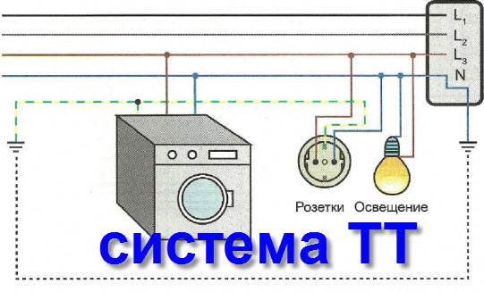
The connection scheme according to the TT system provides direct connection of live parts with the ground, while all open parts of the electrical installation with the presence of current are connected to the ground circuit through a ground electrode, which does not depend on the neutral wire of the generator or transformer.
The IT system protects the unit, arranges grounding and grounding. What is the difference between this connection and the previous diagram? In this case, the transfer of excess voltage from the housing and open parts occurs to the ground, and the source neutral, isolated from the ground, is grounded using devices with high resistance. This circuit is installed in special electrical equipment that must have increased safety and stability, for example, in medical institutions.
Types of zeroing systems
The PNG grounding system is simple in design; in it, the neutral and protective conductors are combined along their entire length. It is for the combined wire that the indicated abbreviation is used. The disadvantages include increased requirements for the coordinated interaction of potentials and conductor cross-section. The system is successfully used for zeroing asynchronous units.
It is not allowed to perform protection according to this scheme in group single-phase and distribution networks. It is prohibited to combine or replace the functions of neutral and protective cables in a single-phase DC circuit. They use an additional neutral wire marked PUE-7.

There is a more advanced grounding system for electrical installations powered by a single-phase network. In it, a combined common conductor PEN is connected to a current source. The separation into N and PE conductors occurs at the point where the main line branches into single-phase consumers, for example, in the access panel of an apartment building.
In conclusion, it should be noted that protecting consumers from electric shock and damage to electrical household appliances during voltage surges is the main task of energy supply. The difference between grounding and grounding is explained simply; the concept does not require special knowledge. But in any case, measures to maintain the safety of household electrical appliances or industrial equipment must be carried out constantly and at the proper level.
My bitter experience as an electrician allows me to say: If your “grounding” is done correctly - that is, in the panel there is a place for connecting "grounding" conductors, and all plugs and sockets have "grounding" contacts - I envy you, and you have nothing to worry about worry.
Grounding connection rules
What is the problem, why can’t you connect the ground wire to heating or water supply pipes?
In reality, in urban conditions, stray currents and other interfering factors are so great that anything can end up on the heating radiator. However, the main problem is that the tripping current of the circuit breakers is quite high. Accordingly, one of the options for a possible accident is a short-circuit breakdown of a phase to the housing with a leakage current just somewhere on the border of the machine’s operation, that is, at best 16 amperes. Total, we divide 220V by 16A - we get 15 ohms. Just some thirty meters of pipes, and you get 15 ohms. And the current flowed somewhere, towards the uncut forest. But that doesn't matter anymore. The important thing is that in the neighboring apartment (which is 3 meters away, not 30, the voltage on the tap is almost the same 220), but in, say, sewer pipe- real zero, or so.
And now the question is - what will happen to the neighbor if he, sitting in the bathroom (connected to the sewer by opening the plug) touches the tap? Did you guess it?
The prize is prison. Under an article about violation of electrical safety rules resulting in casualties.
We must not forget that you cannot imitate a “grounding” circuit by connecting the “zero working” and “zero protective” conductors in a European socket, as some “craftsmen” sometimes practice. Such a replacement is extremely dangerous. It is not uncommon for the “working zero” in the shield to burn out. After this, on the body of your refrigerator, computer, etc. 220V is placed very firmly.
The consequences will be approximately the same as with a neighbor, with the difference that no one will be held responsible for this except the one who made such a connection. But as practice shows, this is done by the owners themselves, because... They consider themselves sufficient specialists not to call electricians.
"Grounding" and "grounding"
One of the options for “grounding” is. But not as in the case described above. The fact is that there is a zero potential on the switchboard body on your floor, or more precisely, the neutral wire passing through this very switchboard simply has contact with the switchboard body through a bolted connection. Neutral conductors from the apartments located on this floor are also connected to the shield body. Let's take a closer look at this point. What we see is that each of these ends is threaded under its own bolt (in practice, however, these ends are often connected in pairs). This is where we need to connect our newly made conductor, which will later be called “grounding”.
This situation also has its own nuances. What prevents the “zero” from burning out at the entrance to the house. Actually, nothing. We can only hope that there are fewer houses in the city than apartments, and therefore the percentage of occurrence of such a problem is much lower. But this is again a Russian “maybe”, which does not solve the problem.
 Only correct solution, in this situation. Take a metal corner 40x40 or 50x50, 3 meters long, hammer it into the ground so that they don’t stumble over it, namely, dig a hole two shovel bayonets deep and drive our corner there as much as possible, and from it draw a PV-3 wire (flexible , stranded), with a cross-section of at least 6 mm. sq. to your switchboard.
Ideally, it should consist of 3 - 4 corners, which are welded with a metal strip of the same width. The distance between the corners should be 2 m.
Just don’t drill a hole in the ground with a meter-long drill and lower the pin there. It is not right. And the efficiency of such grounding is close to zero.
But, as with any method, there are downsides. You are, of course, lucky if you live in a private house, or at least on the first floor. But what about those who live on the 7th-8th floor? Should you stock up on 30-meter wire?
So how to find a way out of this situation? I’m afraid that even the most experienced electricians will not give you the answer to this question.
What is required for house wiring
For wiring around the house, you will need a copper grounding wire of appropriate length and a cross-section of at least 1.5 mm. sq. and, of course, a socket with a “grounding” contact. Box, plinth, bracket - a matter of aesthetics. The ideal option is when you are doing renovations. In this case, I recommend choosing a cable with three cores in double insulation, preferably VVG. One end of the wire goes under the free bolt of the distribution board bus connected to the panel body, and the other end goes to the “grounding” contact of the socket. If there is an RCD in the panel, the grounding conductor should not have contact with the N conductor anywhere on the line (otherwise the RCD will trip).
We must also not forget that the “earth” has no right to be broken by means of any switches.
Even experienced electricians sometimes find it difficult to answer a seemingly simple question: What is the difference between grounding and neutralizing??
Mikhail Vanyushin wonderfully explained the essence of grounding and zeroing in his video course, I highly recommend it to all electricians to study.
I still propose to define what grounding is, what grounding is and find out what they have in common and what exactly distinguishes these concepts.
As Comrade Stalin said, “There is an opinion” that:
The difference is in the physics of the protective action: grounding is intended to reduce the touch voltage to safe values, and grounding should trigger the protection and thus turn off the emergency installation.
In most cases, we are dealing with grounding, which is mistakenly called grounding.
However, there is one caveat: everything written above applies to TN-.. systems; if the systems are TT or IT, then the PE conductor “lives its own life”.
And since the most common grounding system in our country is TN, then I will argue based on the use of TN type systems.
Strictly speaking, the concept of “grounding” according to the rules is only an action, that is, a connection using a grounding conductor - electrodes of a grounding device with a bus GZSH (RE). Here it is probably more correct to say “grounding wire” or “protective neutral conductor”.
If we are talking about a PE conductor, then we understand that we have done something somewhere PEN division on PE and N and we definitely have, well, at least there should be a re-grounding circuit in the ASU. There is a GZSH (well, or PE bus) organized where the zero from the input cable (PEN conductor) is connected.
In this case, all conductive parts are grounded. Or maybe they're nullified? Or is it the same thing?
Let's figure out what it is concept of “zeroing”. I’ll now try to formulate this concept from memory as I understand it, if I’m wrong, then you, fellow electricians, will correct me.
Zeroing- this is a deliberate connection (that is, not an emergency, but we specifically connect) all current-carrying parts of an electrical installation with a solidly grounded neutral of the power source, that is, a transformer, and specifically a three-phase transformer, since a single-phase naturally has no neutral.
And this neutral comes to us at the ASU or metering panel via a PEN conductor, for which there are certain requirements.
That is, to ground, we need to connect all the conductive parts of our house or apartment, and these are the housings of electrical appliances, such as a washing machine or a computer or a refrigerator, to this PEN conductor. Well, if we have a three-wire electrical wiring, then it is natural that we connect the yellow-green PE wire with the PEN wire in the control room, which, as we remember, is screwed to the main or PE bus.
So it turns out that this is the same thing: grounding and grounding?? In both examples I gave, the scheme turns out to be absolutely the same!
So it’s like they used to say before - “When we say party we mean Lenin, when we say Lenin we mean party”, so here it turns out that we say, we mean zeroing, we say zeroing- we mean?
Does it make any difference at all?
Here I pulled out PUE-6 from 1985 from my bins and what I dug up on this issue.
clause 1.1.32: The safety of service personnel and unauthorized persons must be ensured by:
-use of double insulation
- maintaining appropriate distances to live parts or by closing, fencing live parts
-use of device locking and fencing devices to prevent erroneous operations and access to live parts
- reliable and fast automatic shutdown of parts of electrical equipment that accidentally become energized and damaged sections of the network, including protective shutdown
- grounding or grounding of electrical equipment housings and electrical installation elements that may be energized due to insulation damage
-application of isolation transformers
- application of voltage 42 V and below alternating current with a frequency of 50 Hz and 110 V and below direct current
-use of warning alarms, inscriptions and posters;
-use of devices that reduce the intensity of electric fields;
- use of protective equipment and devices, including for protection against the effects of electric fields in electrical installations in which its intensity exceeds permissible standards.
Highlighted important points for us bold.
That is, in the old rules there was no such thing as direct or indirect touch, and it was simply about security people, in the event of deterioration or damage to the insulation, the damaged area must automatically disconnected, and the electrical installation must be grounded or neutralized.
Go to chapter 1.7 “Grounding and protective measures for electrical safety”
Here is the definition of grounding according to PUE-6:
clause 1.7.6: Grounding of any part of an electrical installation or other installation is called deliberate electrical connection of this part to the grounding device.
clause 1.7.7: Protective grounding is the grounding of parts of an electrical installation to ensure electrical safety.
The difference from PUE-7 is that the new rules add that grounding is a deliberate connection of any kind network points, but the rest remained as before.
And now the most important thing is the definition of zeroing according to PUE-6:
clause 1.7.9: Zeroing in electrical installations up to 1 kV it is called the deliberate connection of parts of an electrical installation, normally not energized, with solidly grounded transformer neutral or a generator in three-phase current networks, with a solidly grounded output of a single-phase current source, with a solidly grounded midpoint of the source in DC networks.
The difference between this definition and the definition of zeroing according to the new PUE-7 is, firstly, that in the new rules zeroing is called protective zeroing, and not simply by zeroing as in PUE-6, and secondly, in the new PUE there are no words “normally not energized”.
There are no more differences between the old and new PUE! That is, in principle, it remains as before - all current-carrying housings of the electrical receiver are connected to the solidly grounded neutral of the current source, for example, in a floor panel they were previously connected to the neutral core of the input cable.
According to PUE-6, there were no such definitions as PEN, PE, and N-conductors, but simply zero protective and zero working conductors, and in paragraph 1.7.18 there was a clarification that:
“In electrical installations up to 1 kV with a solidly grounded neutral, zero worker the conductor can perform the functions of a zero protective conductor"
Difference in Definition neutral protective conductor between PUE-6 and PUE-7 is that according to PUE-6 this conductor is connected to a solidly grounded neutral “zeroable parts” in electrical installations, and in PUE-7 the protective neutral conductor connects to the solidly grounded neutral of the transformer “exposed conductive parts of an electrical installation”.
These are the definitions:
PUE-6 clause 1.7.17: The neutral protective conductor in electrical installations up to 1 kV is the conductor connecting the grounded parts with the solidly grounded neutral of a transformer or generator in three-phase current networks, with the solidly grounded output of a single-phase current source, with the solidly grounded midpoint in the direct current source.
PUE-7 clause 1.7.34: Protective (PE) conductor-conductor, intended for electrical safety purposes.
Protective grounding conductor is a protective conductor designed for protective grounding.
Protective potential equalization conductor - a protective conductor designed for protective potential equalization.
Neutral protective conductor is a protective conductor in electrical installations up to 1 kV, intended for connecting open conductive parts to the solidly grounded neutral of the power source.
Noteworthy in PUE-6 is the fact that it was forbidden to use electrical installations without grounding:
clause 1.7.39: In electrical installations up to 1 kV with a solidly grounded neutral or a solidly grounded output of a single-phase current source, as well as with a solidly grounded midpoint in three-wire DC networks zeroing must be performed.
The use in such electrical installations of grounding the housings of electrical receivers without grounding them not allowed.
Also, according to the old rules, it was allowed to use the neutral working wire for grounding, paragraph 1.7.73 speaks about this:
“As neutral protective conductors, they should first of all be used zero working conductors…”
However, this did not mean that this was possible for portable electrical receivers; clause 1.7.82 clearly stated this:
“It is not allowed to use neutral working conductors going to portable power receivers as neutral protective conductors single-phase and direct current. To ground such electrical receivers, a separate third conductor, connected in the plug-in connector of a branch box, in a panel, shield, assembly, etc. to the zero working or zero protective conductor.”
Even in the old PUE-6 there was an interesting clause 1.7.84, according to which it was possible to use the working neutral wire of the lighting line for zeroing electrical equipment powered from other lines.
That is, it was possible to stupidly find the neutral wire from the lamp and use it to ground electrical equipment housings, although the following conditions specified in this paragraph had to be met:
“Clause 1.7.84: Neutral protective conductors of lines are not allowed to be used to neutralize electrical equipment powered by other lines.
It is allowed to use zero working conductors lighting lines for zeroing electrical equipment powered by other lines, if all of these lines are powered by one transformer, their conductivity satisfies the requirements of this chapter and the possibility of disconnecting the neutral working conductors during operation of other lines is excluded.
In such cases, switches that disconnect neutral working conductors together with phase conductors should not be used.”
If we talk about residential premises, then clause 7.1.59 explained what should have been nullified according to the old rules:
“Clause 7.1.59: In residential and public buildings must be zeroed metal cases of stationary electric stoves, boilers, etc., as well as portable household ones electrical appliances and machines with a power of more than 1.3 kW and metal pipes for electrical wiring.
For zeroing housings of stationary single-phase electric stoves, household air conditioners, electric towels, etc., as well as portable household appliances and machines with a power of more than 1.3 kW must be laid from the riser, floor or apartment panel separate conductor cross-section equal to the cross-section of the phase conductor.
This conductor is connected to the neutral protective conductor of the power supply network before counter (input side) and before switching off device (if any).”
However, even according to the old rules, it was forbidden to make a jumper from the working zero to the grounding for an electric stove! - here is this point:
clause 7.1.60: Grounding a three-phase electric stove should be carried out using an independent conductor, starting from the group panel (distribution point). The use of a neutral working conductor to ground a three-phase electric stove is prohibited.
So, now we can draw some conclusions.
1. Both grounding and grounding are performed for electrical safety purposes.
2. Such concepts as grounding and zeroing were both in the old rules of PUE-6 and in the new rules of PUE-7.
3. Grounding differs from grounding in that when grounding we connect the grounded parts not only to the grounding device, but also to solidly grounded neutral of the current source.
That is, if we have electrical wiring in the house made according to the new rules, there is a division into PE and N, then by connecting the body of the electric heater to the PE bus we thus ground and let's zero! Since in the end the PE bus is still connected to us either in the ASU or in the metering panel with the PEN wire at the entrance to the house. And the PEN conductor, in turn, is connected to the solidly grounded neutral of the transformer at the substation.
So it turns out that this is the same concept - protective grounding And protective grounding.
We say grounding, we mean grounding, we say grounding, we mean grounding
Some may have a question: well, if this is the same thing, then why do we do grounding at all, that is, connect the grounded parts to the solidly grounded neutral of the transformer?
I answer: this is done so that when a phase wire is shorted to the body of an electrical appliance, a short circuit current will occur and its value will be very high, so that its value will be sufficient to trigger the protection circuit breaker.
Imagine for yourself - when the phase of the power supply is short-circuited to its own solidly grounded neutral, this source is short-circuited, that is, to itself or, to make it even clearer, to the minimum load resistance, and since there is no load, the short-circuit current tends to almost infinity and is limited only by the active internal resistance of the transformer itself and the connecting wires.
Therefore, for example, with a load of 25 amperes, the short circuit current in the electrical wiring can reach 500 and 1000 amperes, which is quite enough to trip the circuit breaker.
A machine with characteristic “C” (the most common) turns off during a short circuit with a multiple of 5-10 of the rated current, that is, for example, a 25-amp machine will turn off at 125 to 250 or more amperes, and if the short-circuit current is 500 amperes, then this machine will work reliably and turn off the damaged area, since this value is more than enough to trigger the electromagnetic release of the machine.
What will happen if you don’t do grounding, but simply connect it to a grounding device, you ask. But then we may not receive a short circuit current and our circuit breaker simply will not work and will not turn off the damaged area, which can lead not only to the failure of electrical equipment and wiring, but also to a fire...
The fact is that the resistance of the grounding device is very high, at least significantly higher than the internal resistance of the source current transformer with all wires connected.
In this case, when the phase wire is short-circuited to the body of the electrical appliance, the current will flow through the grounding device into the ground and at the same time the value of the electric current will increase slightly (well, unless, of course, you have a ground electrode in a deep-water well with a resistance of less than 1 Ohm)
Let's say you have a re-grounding circuit with a resistance of 10 ohms, then the current will flow:
I=U/R=230:10=23 amperes
Even a 16-amp circuit breaker with such a current will not turn off immediately, and may not turn off at all, and this despite the fact that the machine will be completely serviceable, it is simply designed in such a way that this current value is not enough for it to turn off. According to GOST, the machine must withstand a current of 1.42 of the rated current for an hour and not turn off, and for this machine this is what happens:
16*1.42=22.72 amperes
So it turns out that without grounding there seems to be damage (phase short circuit to the housing) and the protective equipment will be in good working order, and the damaged area will automatically won't turn off that's right contradicts requirements of PUE-7.
I will be glad to see your comments, if you have any technical questions, please ask them on the forum, that’s where I answer questions - .
Subscribe to my channel on YouTube !
Latest video from the “Electrician Tips” channel:
Watch many more home electrical videos!
Be the first to know about site news!
When purchasing any electrical equipment, be it washing machine or a refrigerator, it is not designed for a lifetime of service and during operation, like any other equipment, it can break down. To protect electrical equipment from abnormal operating conditions (overload or short circuit), various protective devices are used (automatic devices, plugs, etc.)
But there are situations when protective devices do not respond to damage that occurs. One of these cases is damage to the internal insulation and the appearance of high voltage on the metal casing of equipment.
In this case, protection is necessary for the person himself, who becomes energized by touching the damaged equipment. To protect against such damage, grounding was invented, the main purpose of which is to reduce the magnitude of this voltage.
That is, the main thing purpose of grounding- reduce touch voltage to a safe value.
Let's assume that you have at home ceiling lamp, the body of which is not connected to ground. Due to damage to the insulation, the metal part of the lamp became energized. The moment you try to change the light bulb, you will be shocked, because by touching the body you become a conductor and the electric current will flow through your body into the ground.
If the lamp is grounded, most of the current will flow into the ground along the grounding wire and at the moment of contact, the voltage on the body will be much less, and accordingly the amount of current passing through you will also be less.
Grounding- is called the connection of metal non-current-carrying parts of an electrical installation with the ground (ground loop) which are not normally energized, but may become energized due to insulation damage.
Also, grounding is necessary for the functionality of devices such as RCDs. If the housings of the electrical installations are not connected to the ground, then no leakage current will flow, which means the RCD will not respond to a fault.
The difference between grounding and grounding
Along with grounding, you have probably heard the term grounding.
Zeroing- is called the connection of metal non-current-carrying parts of an electrical installation with a zero (neutral conductor of the network).
In my own way purpose grounding and grounding perform the same task - protect a person from electric shock. However, they provide this protection in slightly different ways. In networks with grounding, electrical equipment is disconnected from the network, the casing of which is energized due to an insulation breakdown.
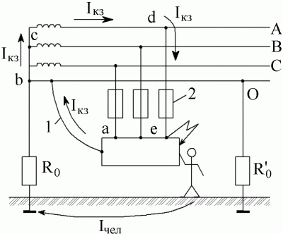
Let's consider an example in which protection of an electrical installation is ensured using grounding.
As can be seen from the figure, when a phase breaks down on a housing connected to zero, a closed circuit appears between phase and zero, that is, a single-phase short circuit. When a short circuit occurs, protective devices such as circuit breakers or fuses react, resulting in the disconnection of the damaged electrical installation from the power source.
The examples discussed above make it possible to conclude that:
Surely you have asked in what cases protection is performed by grounding, and in which by grounding. The use of grounding and grounding in different cases is caused by different grounding systems for electrical installations. In electrical installations with voltages up to 1000 V, five grounding systems are used: TN-C, TN-S, TN-C-S, TT, IT.
Grounding is used as protection in systems that contain PEN, PE or N conductor. These are networks with a solidly grounded neutral, TN-C, TN-S and TN-C-S.
Grounding is used in electrical installations with TT and IT grounding systems.
The grounding and grounding methods discussed above are more suitable for use in industrial electrical installations in production. You can consider in more detail the connection and installation of grounding for household electrical installations here: grounding in an apartment and grounding in a private house.
Our whole life is inseparable from all kinds of electrical devices. Failure of any electrical equipment is a frequent and completely normal occurrence; no device can work forever and without a single failure. Our task is to protect these electrical assistants from short circuits or overloads occurring in the circuit, and ourselves from damage to the body from high voltage. In the first case, all kinds of protective devices come to the rescue, but to protect people, grounding and grounding of electrical installations are used. This is one of the most difficult parts of electrical engineering, but we will try to figure out what is the difference between these works, and in what cases it is necessary to apply certain protective measures.
If circuit breakers, plugs and other protective devices do not respond to a fault, and as a result a breakdown of the internal insulation occurs, increased voltage appears on the metal body of the installation. A person touching such a device can lead to muscle paralysis (at a current strength of 20-25 mA), preventing independent separation from contact, arrhythmia, disturbances in blood flow (at 50-100 mA) and even death.
If parts of the electrical installation must be energized due to technical features, then they must be protected in accordance with generally accepted safety precautions, for example, with special casings, barriers or mesh barriers. In order to prevent accidental electric shock when the insulating layers are damaged, protective grounding and grounding are used. To understand the difference between grounding and grounding, you need to know what they are.
What is grounding
Often, novice electricians do not quite understand what the difference between grounding and grounding is. Grounding is the connection of an electrical installation to the ground in order to reduce touch voltage to a minimum. It is used only in networks with isolated neutral. As a result of installing grounding equipment, most of the current entering the housing should go through the grounding part, the resistance of which should be less than other sections of the circuit.
But this is not the only function of grounding. Protective grounding electrical installations also contributes to an increase in emergency short circuit current, no matter how much this contradicts its purpose. When using a grounding conductor with a high resistance value, the fault current may be too low to trigger the protective devices, and the installation will remain energized in an emergency, posing a huge danger to humans and animals.
The ground electrode with conductors forms a grounding device, where it is, in fact, a conductor (group of conductors) connecting the conductive parts of installations to the ground. Based on their purpose, these devices are divided into the following groups:
- lightning protection, for discharging pulsed lightning current. Used for grounding lightning rods and arresters;
- workers to maintain the required operating mode of electrical installations, both in normal and emergency situations;
- protective, to prevent damage to living organisms by electric current that occurs when a phase wire breaks down on the metal body of the device.
All grounding electrodes are divided into natural and artificial.
- Natural ones are pipelines, metal structures of reinforced concrete structures, casing pipes and others.
- Artificial grounding conductors are structures constructed specifically for this purpose, that is, steel rods and strips, angle steel, substandard pipes, and more.
Important: pipelines of flammable liquids and gases, pipes coated with anti-corrosion insulation, aluminum conductors and cable sheaths are not suitable for use as natural grounding. It is strictly forbidden to use water and heating pipes as grounding conductors in residential premises.
Classification of grounding systems
Depending on the connection diagram and the number of neutral protective and working conductors, the following grounding systems for electrical installations can be distinguished:
- TN-C;
- TN-C-S;
The first letter in the name of the system indicates the type of grounding of the power source:
- I – live parts are completely isolated from the ground;
- T – the neutral of the power supply is connected to ground.
By the second letter you can determine how the exposed conductive parts of the electrical installation are grounded:
- N – direct connection with the grounding point of the power source;
- T – direct connection to the ground.
The letters immediately following N, separated by a hyphen, indicate the method of constructing protective PE and working N neutral conductors:
- C – conductor functions are provided by one PEN conductor;
- S – conductor functions are provided by different conductors.
Legacy TN-C system
This grounding of electrical installations is used in three-phase four-wire and single-phase two-wire networks, which predominate in old-style buildings. Unfortunately, this system, despite its simplicity and accessibility, does not allow achieving a high level of electrical safety and is not used in newly constructed buildings.
For the modernization of old houses TN-C-S
Protective grounding of electrical installations of this type is used mainly in reconstructed networks, where the working and protective conductors are combined in the input device of the circuit. In other words, this system is used if in an old building where TN-C type grounding is used, it is planned to locate computer equipment or other telecommunications, that is, to make the transition to the TN-S system. This relatively inexpensive scheme has a high level of security.
The TN-C-S system allows you to move from the legacy TN-C to TN-S
Specifics of the TN-S system
This system differs in the location of the neutral and working conductors. Here they are laid separately, and the neutral protective conductor PE connects all conductive parts of the electrical installation at once. To avoid repeated grounding, it is enough to arrange a transformer substation with basic grounding. In addition, such a substation allows you to achieve a minimum length of the conductor from the cable entry into the electrical installation to the grounding device.
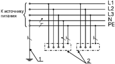
1. Ground electrode;
2. Conductive parts of the installation.
TT system, features
A system where all current-carrying open parts are directly connected to the ground, and the grounding conductors of the electrical installation are not electrically dependent on the neutral grounding conductor of the substation, is called TT.
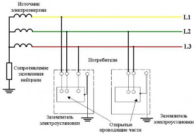
The TT grounding system is characterized by the presence of grounding conductors for each current-carrying part of the installation
Characteristic differences of the IT system
The difference between this system is the isolation of the neutral of the power source from the ground or its grounding through devices with high resistance. This method allows you to minimize the leakage current to the housing or to the ground, so it is better to use it in buildings where strict electrical safety requirements are established.
What is zeroing
Zeroing is a connection metal parts, not under voltage, either with a grounded neutral of a step-down three-phase current source, or with a grounded output of a single-phase current generator. It is used so that if the insulation breaks down and current enters any non-current-carrying part of the device, a short circuit occurs, leading to rapid operation of the circuit breaker, blown fuses or reaction of other protection systems. Mainly used in electrical installations with a solidly grounded neutral.
Schematic diagram zeroing electrical installations
Additional installation of an RCD in the line will lead to its operation as a result of the difference in current strength in the phase and neutral working wires. If both an RCD and a circuit breaker are installed, a breakdown will result in either both devices tripping or a faster-acting element turning on.
Important: When installing grounding, it is necessary to take into account that the short circuit current must necessarily reach the value of melting the fuse insert or tripping the circuit breaker, otherwise the free flow of short circuit current through the circuit will lead to voltage on all grounded housings, and not just on the damaged area. Moreover, the value of this voltage will be equal to the product of the resistance of the neutral conductor and the circuit current, and therefore extremely dangerous for human life.
The serviceability of the neutral wire must be monitored very carefully. Its break leads to the appearance of voltage on all neutralized housings, since they are automatically connected to the phase. That is why it is strictly prohibited to install any protective equipment (switches or fuses) into the neutral wire that would cause it to break when triggered.
In order to reduce the likelihood of electric shock when the neutral wire breaks, repeated groundings are performed every 200 m of the line. The same measures are taken at the end and input supports. The resistance of each repeated grounding conductor should not exceed 30 Ohms, and the total resistance of all such groundings is 10 Ohms.
Grounding and grounding: what is the difference?
The main difference between grounding and grounding is that when grounding, safety is ensured by a rapid decrease in current voltage, and when grounding, by disconnecting the section of the circuit in which a breakdown of current occurred to the housing or any other part of the electrical installation, while in the time interval between the closure and the termination When power is supplied, the potential of the electrical installation housing decreases, otherwise an electric current discharge will pass through the human body.
![]()
Electrical diagram grounding and grounding
Requirements for grounding (grounding)
In all electrical installations where the neutral is isolated, protective grounding must be performed, and the ability to quickly search for ground faults must also be provided.
If the device has a solidly grounded neutral and its voltage is less than 1000 V, then only grounding can be used. When equipping such an electrical installation with a separating transformer, the secondary voltage should be no more than 380 V, the step-down voltage should be no more than 42 V. In this case, only one electrical receiver with a rated current is allowed to be powered from the separating transformer protective device no more than 15 A. In this case, grounding or grounding of the secondary winding is prohibited.
If neutral three-phase network up to 1000 V is isolated, then such electrical installations must have protection against breakdown as a result of damage to the insulation between the windings of the transformer and a breakdown fuse, which is mounted in the neutral or phase on the lower voltage side.
What and when needs to be grounded
Protective grounding and grounding of electrical installations must be carried out in the following cases:
- With an alternating rated voltage over 42 V and a constant rated voltage over 110 V, especially dangerous and outdoor installations.
- With alternating voltage over 380 V and constant voltage over 440 V in any electrical installations.
The housings of electrical installations, device drives, frames and metal constructions distribution cabinets and panels, secondary windings of transformers, metal sheaths of cables and wires, cable structures, busbar ducts, boxes, cables, steel pipes electrical wiring and electrical equipment located on moving parts of mechanisms.
In residential and public buildings, electrical appliances with a power of over 1300 W must be grounded (grounded). If suspended ceilings are made of metal, then it is necessary to ground all metal housings of lighting fixtures. Bathtubs and shower trays made of metal must be connected to water pipes with metal conductors. This is done to equalize electrical potentials. To ground the housings of air conditioners, electric stoves and other electrical appliances whose power exceeds 1300 W, a separate conductor is used, connected to the neutral conductor of the power supply network. Its cross-section and the cross-section of the phase wire laid from the distribution board must be equal.
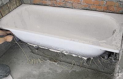
To equalize electrical potentials, the bath must be short-circuited. water pipes
A complete list of equipment that requires grounding or zeroing, as well as devices where, on the contrary, these protective measures can be neglected, can be found in the PUE (Electrical Installation Rules). Here you can find all the basic rules for grounding electrical installations.
The grounding and grounding device is a very responsible job. The slightest error in calculations or neglect of a seemingly insignificant requirement can lead to a great tragedy. Only people who have necessary knowledge and work experience.