
Dismantling and modification of Chinese LED lamps
There are enough publications on our website dedicated to light sources. These are, first of all, incandescent lamps; here we have found a solution to protect them from burnout and extend their service life. Perhaps they still remain the most widespread source of light, and the reason here is not only accessibility, but also that the spectrum of their radiation is most pleasing to the eye. Besides ordinary light bulbs, the so-called “energy saving” - compact fluorescent lamps. We have provided a description of repair methods and modifications that also increase service life. However, LED light sources should also be considered as they are gaining popularity.
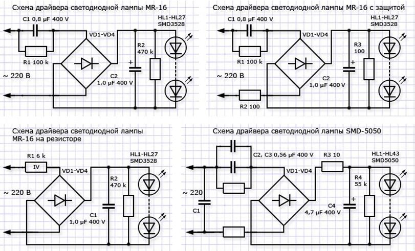
An LED lamp consists of several LEDs (or an LED matrix) with a power circuit contained in a base. Proper nutrition LEDs are a whole science, fortunately, there are plenty of mains power drivers, from specialized microcircuits to simple circuits with two transistors. However, manufacturers very rarely take advantage of the advances in circuit technology and modern electronics, preferring to power LEDs out of habit - through a ballast (quenching) capacitor.
For the study, three 3W LED lamps made in China were purchased at a price of 35 rubles per piece.
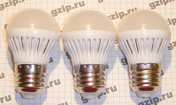
The body is made of plastic, the diffuser in the form of a hemisphere is also plastic, it is attached without glue, it simply snaps into place. To disassemble an LED lamp, just pry the diffuser in a circle and disengage it from the lamp body. This releases the printed circuit board with parts.

Two of the three lamps have one wire missing, otherwise the installation is more or less neat. Quenching capacitor marked 824 - 820 nF (0.82 µF), 400 V. 9 LEDs of a size similar to 3528, only thinner, connected in series. The bridge is assembled from four diodes marked M7.
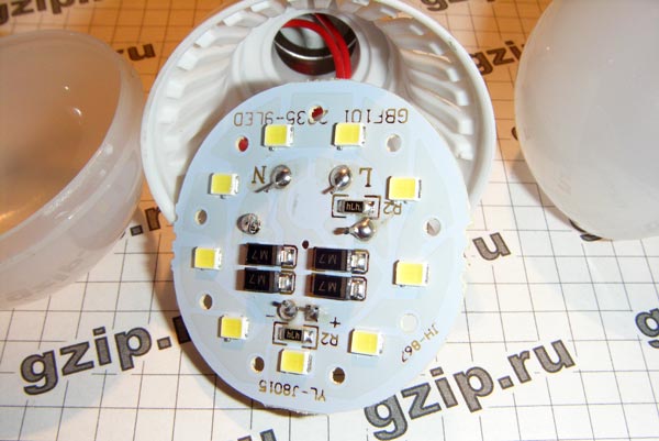
One such lamp shines very weakly. With a lamp power of 3W, its light should be comparable to an incandescent lamp with a power of 20-25W. These lamps shine more dimly, which seems to hint to us at the need for measurement, which will be done soon, at the same time the need for improvement will be clarified - is there a significant current surge when turned on, do the LEDs work, as they say, “overheating”?
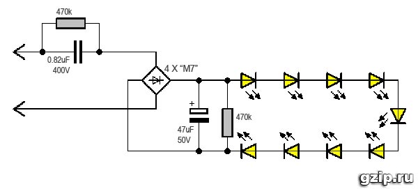
The LED lamp circuit is simple. As already mentioned, the LEDs are powered through a quenching capacitor.
Simulation shows that a current of 32mA flows through the LEDs, the total voltage drop across the chain of nine LEDs is 26V, so their power consumption is 0.8W, which is three times less than stated.
These lamps are sold as three-watt lamps. Of course, their real power is three times less. Each lamp contains 10 2835 LEDs. Judging by the datasheets, these LEDs allow current up to 150mA with good heat dissipation. In this particular case, the whole thing is powered through a ballast capacitor with a capacity of 0.82 μF and a 100 ohm resistor connected in series. Shorting the resistor does not have a significant effect on the brightness of the glow. The lamps shine very dimly.
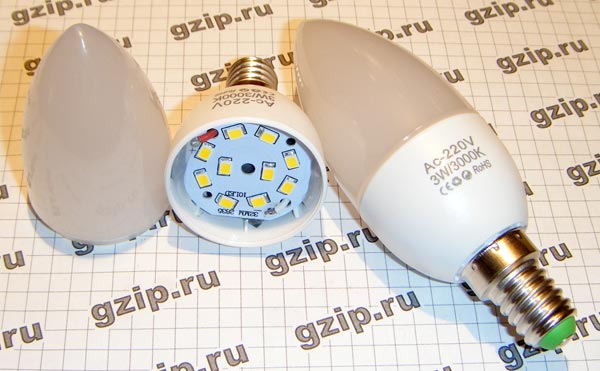
It can be disassembled by simply tilting the matte diffuser to the side. The LED board is secured with silicone glue.
The following modification was planned: to increase the capacity of the ballast capacitor in order to increase the current. For testing, a capacitor with a capacity of 1.5 μF was installed. In this case, the aluminum substrate of the LEDs became excessively hot. Therefore, modification of these lamps was impossible.
The following lamps are more honest products of Uncle Liao. The lamp is designed for 12 volt power supply (halogen power supplies). The case is also a radiator made of honest aluminum.

The lamps are made on the basis of 1-watt LEDs connected in series. Inside the base there is an ultra-compact stabilizer of who knows what, which (attention!) does not work. The brightness of the lamps varies depending on the supply voltage. And this despite the fact that the famous MC34063 and XL6001 are hidden under the heat shrink in one of the lamps.
It can be disassembled by unscrewing the top and bottom parts.
Possible alteration: convert to 220 volts and a “human” base. This requires alteration of the lamp design.
Processing of large corns. The lamps themselves are easy to disassemble - by removing the plastic ring at the end. It is fixed using small rods, some of which can be glued. They will have to be torn off. When the ring is removed, a round platform with LEDs will be released. Inside the lamp there is a small board with a capacitor ballast, on which an electrolytic capacitor with a capacity of 4.7 μF is installed. This capacity is clearly not enough for the given lamp power, resulting in flickering that is invisible to the eye. There is another, not obvious drawback: the small capacity of this electrolyte is an insufficient load for the capacitor ballast at the beginning of operation. As you know, a discharged capacitor has zero resistance and when the lamp is turned on, a voltage surge occurs, which may well burn out some LED. To protect against this unpleasant phenomenon, you should install a capacitor with a larger capacity, which will provide the necessary voltage drop when turned on, or shunt the LEDs with a zener diode. The second option is more complex (you also need to find a zener diode for a relatively high voltage) and does not eliminate flickering, so the obvious modification is to install an electrolytic capacitor of larger capacity.
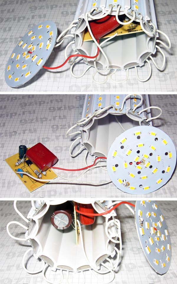
Initially, the payment is not received, because connected by short wires to the lamp base. Pushing it out as far as possible, we unsolder the wiring. It is quite possible to do this. We solder the 4.7 µF capacitor and install a more capacitive one in its place, in this case - 68 µF 450V. The space inside the lamp allows it to be installed with reverse side fees. We don’t install a zener diode yet - we drive the lamp like this.
Everything is put together in reverse order. It should also be remembered that a lamp with a capacitor ballast is galvanically connected to the network and is dangerous. Therefore, it will not be superfluous to glue or draw the appropriate symbols to avoid touching live parts. Actually, almost the entire lamp contains such parts. When installing or removing it, you need to hold it very carefully, using the plastic ring.
Repairing 220-volt LED lamps, if desired, can be done at home, but for this you definitely need to have a soldering iron and a multimeter.
LED lamps of this type are called “LL-CORN” in English, which means (corn lamp), in appearance it really looks like an ear of corn. These “cobs” are available in many types. It is difficult to choose truly high-quality products. Most of these light bulbs are made in China and are fakes, but this article will not be about the fight against counterfeit products, but we will talk about the topic: repair of LED corn lamps.
Lamps of the same type as in the photo are produced with 24, 30, 36, 48, 56, 69, 72 LEDs. Currently, these lamps are equipped with SMD5730 or SMD5733 LEDs. Their details:
SMD5730 – dimensions are indicated in the name 5.7 mm. by 3.0 mm. Power – 0.5 watt. Voltage 3.4 volts. Current 150 mA. Luminous flux 30 – 45 lumens.
SMD5733 – dimensions are indicated in the name 5.7 mm. at 3.3 Power – 0.5 watts. Voltage 3.4 volts. Current 150 mA. Luminous flux 35 – 50 lumens. But it must be said that LEDs produced in China often do not correspond to the declared characteristics.
If an LED lamp stops shining, then it does not need to be thrown away immediately; repairing such a lamp is not difficult and can be done by almost anyone who knows how to hold a soldering iron in their hands. But before repairing the lamp, you need to make sure that the lamp received power in the place where it stood. This means that in place of the unscrewed lamp you need to screw in another one and make sure that it is the lamp that is not working, and not the lamp itself.
To repair, you need to get to the insides, and then the question arises: how to open an LED lamp? The answer is simple - using an ordinary kitchen knife. You need to insert the knife into the place where the lamp body is connected to the protective transparent casing and turn until the groove of the casing comes out of the protrusion of the casing.

The casing will pop out with a slight click.
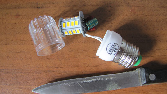
The entire “stuffing” of the lamp opens before us. First of all, we inspect everything inside and make sure that the soldering of the parts is of high quality (if not, then we solder the questionable places). If there are blackened parts, then we replace them with similar ones.
To determine the ratings of the parts, the article below provides a general diagram for such lamps and lists the ratings of the parts, depending on the power of the lamp. If there are blackened LEDs, then they definitely need to be replaced with exactly the same ones. When replacing LEDs, be sure to pay attention to the polarity. If you confuse the plus with the minus, it will not work.
If you have a powerful soldering iron, then to solder small LEDs, you need to wrap a piece of copper wire of a suitable diameter around the soldering iron tip and solder with it.
Swollen capacitor - replace it. There is a crack on the part - we replace it. Crack on printed circuit board– solder a jumper to the circuit tracks or clean off the varnish on both sides of the crack and apply a drop of tin with a soldering iron. If there are no suitable parts, then we leave this burnt out light bulb as a donor for future repairs.
It happens that appearance The parts are normal, but it has internal damage. In this case, you cannot do without a multimeter. We check capacitors for breakdown, and resistors for open circuit. There are few parts in the circuit of LED lamps and checking them all is not difficult.
The exception is lamps where power is provided by drivers made from microcircuits. Repairing an LED lamp driver consisting of micro components can be done at home, but to a limited extent and only professionals can do it. Our lamp has a simple circuit.
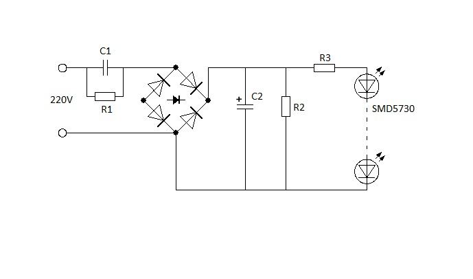
All light bulbs in the series we are considering have the same circuit. Only the number of LEDs and the ratings of some elements differ. For repairs, it is important to know the operating principle of the circuit and what role the parts play. Let's start from the beginning.
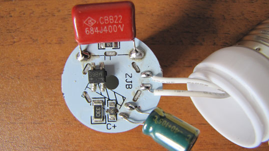
Capacitor C1 is a quenching capacitor and can be replaced exactly the same as in a lamp, rated for 400 volts.
For a lamp with 24 LEDs it is 0.56 microfarads. For a lamp with 30 LEDs – 0.68 µF. 36 – 48 LEDs – 0.82 uF. 56 – 69 LEDs – 1.2 uF. Designated 564J400v, 684J400v, 824J400v, L105J400v, respectively.
Capacitor C2 serves to smooth out ripples of the current rectified by the diode assembly and can be replaced by any polar capacitor from 2.2 to 10 microfarads with a voltage from 100 to 400 volts. But it is better to take these denominations to the maximum. The higher the rating, the less flickering the LEDs will be. Conduct an experiment with your phone camera by pointing the lens at the switched on LED light bulb.
Resistors R1 and R2 serve to discharge the capacitors to which they are connected in parallel, and can be replaced by any from 500 kilo ohms to 1.5 mega ohms.
The diode assembly is used by MB6S and can be replaced by any similar one, or you can use four diodes, for example 1N4007 or any similar ones, connected in a bridge circuit.
Resistor R3 limits the current of the LEDs and its value depends on the number of them in the lamp. 24 – 30 LEDs – 33 ohms. 36 LEDs - 36 ohms. 48 LEDs - two parallel connected at 100 ohms, resulting in 50 ohms. 56 LEDs - 100 ohms. 69 LEDs - two parallel 390 each. You can replace them with the same power or more. The resistance of this resistor determines the current that passes through the LEDs and, therefore, the brightness of their glow. If the resistor value is smaller, the glow will increase, but the service life of the LED will significantly decrease and vice versa.
Now you can do the repair of 220 LED lamps yourself.
Good luck to you in your endeavors.
I've always said LEDs are the future. This is primarily due to their durability and energy savings. However, today, the manufacturing technology of these lamps is not yet perfect, the high price itself speaks of this, and it is too early to purchase this innovation. But no one listens, so they buy it, and then make claims - and lo and behold, it doesn’t work anymore.
But for me it was like a warm-up when a couple of defective lamps were placed on my table.
To tell the truth, this was the first time I looked at these lamps, made of thick glass; they seemed inseparable, which only confirmed my theory about their imperfection, and while I was thinking out loud about this, one of the listeners took a hairdryer and simply heated a glass cylinder and a glued circle of glass along the contour he came out of the hug. At high temperature The linear dimensions increase, and the glue becomes elastic. Two unsoldered LEDs immediately caught my eye (they were raised on one side, this happens when you fall). An electrolytic capacitor exploded in another lamp. But the reason is not only this, but the malfunction of one LED, which, having broken the circuit, thereby turned the voltage on the capacitor equal to 100 volts into a potential difference of 300 volts, which led to the explosion.
Here is the simplest, and therefore the most common, electrical circuit of LED lamps without transformers. Let’s start with it. But first, a little theory.
Capacitor C1 plays the role of a quenching resistor, since at frequency AC has a resistance, but unlike a resistor it does not dissipate heat and serves to reduce the voltage of the series circuit. Sometimes, instead of one capacitor, two are placed in parallel to achieve the required brightness. For reliable operation of the lamp, its operating voltage must be greater than 450 volts.
The diode bridge is used to convert alternating current into direct current.
Capacitor C2 smoothes out the ripple of the 100 Hz rectified bridge voltage. Its operating voltage must be more than 300 volts.
High-resistance resistors R1, R2, in parallel with capacitors C1 and C2, serve the purpose of electrical safety, to remove charges from these capacitors, so that they do not get shocked if you touch the base of a just removed lamp.
Low-resistance resistors R3, R4 are for protective purposes, limiting current surges, in some cases they act as fuses, overheating and failing, opening the power circuit in the event of a short circuit.
Of all the listed radio components, high-resistance resistors and rectifier bridges are the least likely to fail.
Grandfather for a turnip, grandmother for grandfather, etc.
As a rule, one of the LEDs of the matrix often fails due to a short circuit of capacitor C1. When this capacitor is short-circuited, the voltage and current on the LED matrix increases, and the bright glow of the lamp does not last long, until the weakest element of the matrix fails. A failed LED opens the circuit, and the voltage on capacitor C2 reaches 300 volts. Capacitor C2 (its operating voltage was 100 volts), exploding, short-circuits the power circuit and disables low-resistance resistors R3, R4, which instantly heat up from the extremely high current, and their conductive layer cracks, breaking the power circuit.
This is probably the worst fairy tale from my childhood, but the hint remains valid - it is not enough to find the reason for the lack of glow, it is also necessary to find the consequence.
Finding faulty components
So, the lamp is opened. The first thing I did was watch the editing carefully.
1. The simplest thing is that the wire has fallen off the lamp base. This has already happened with energy-saving lamps. The wire itself can be extended, and instead of a soldered or welded connection with an aluminum base, a threaded connection can be used.
2. I simply removed the swollen or burnt out electrolytic capacitor C2. For reliability, I used a capacitor with an operating voltage of more than 300 volts. The lamp will function without it.
3. The tester rang low-resistance resistors R3, R4, the readings should be in the range of 100 - 560 Ohms (101 - 561 designation of chip resistors). One of the resistors did not show its value, so I replaced it.
4. Now it’s the turn of capacitor C1. It is blocked by a protective resistor R1 from 100 kOhm (104) and above 510 kOhm, (514, the last digit of chip resistors implies the number of zeros), the value of which will be shown by an ohmmeter, which indicates the serviceability of the capacitor itself, at least it is not broken. This capacitor must be placed at a voltage of at least 450 volts. Sometimes, in order to reduce dimensions, lamp manufacturers install capacitors at a lower operating voltage, which leads to their failure.
5. Now you can connect the circuit to the network and measure it with a tester constant voltage on capacitor C2 or on conductive areas where it stood. There was no glow, and the constant voltage was 1.4 times greater than the alternating voltage of the 220 volt network and amounted to 308 volts, which indicated a break in the LED matrix, but the serviceability of the diode bridge.
6. I begin the search for a faulty LED with a visual inspection of the lamp disconnected from the network. Externally, such an element differs from others by a black dot on the surface of the crystal. So, the suspected element has been found, but to be sure, you can use a tester and compare the transition resistance of each LED in direct connection. It should be about 30 kOhm.
If all elements of the matrix show the same resistance, and when it is connected, there is no glow, and the constant voltage on capacitor C2 drops sharply to a few volts, then this indicates a malfunction of capacitor C1. Most likely he will be in a cliff.
I don’t recommend doing it the way I did it myself. Wrapping his free hand behind his back, with his other hand, using sharp tweezers near the switched-on lamp, he shorted the conductive pads of each LED in turn, until the entire matrix lights up. It’s so easy to find an element that causes the lamp to dim, flicker, or turn on for a short time. It is possible that the element itself will simply have poor contact with the conductive path due to poor soldering.
 |
| Fig.4. |
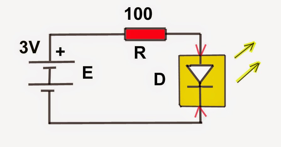
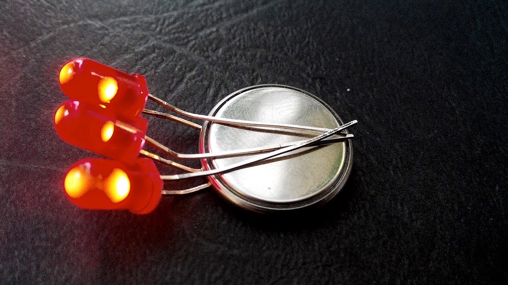
There is another way to check the LED matrix (Fig. 4.). Using power from a container with two batteries with a total voltage of 3 volts or from one battery with the same voltage. Using a series-connected resistor R = 100 Ohm, I connect leads with a voltage of 3 volts in the appropriate polarity to each LED D without removing it from the circuit and make sure that it glows (it will glow only in direct connection).
Attention!
Progress does not stand still, and I came across an LED lamp in which the LEDs are presented in the form of two series-connected semiconductor crystals in one housing, which means that they will not light up at a voltage of 3 volts. To check, the same circuit is used (Fig. 4), only with a container for 4 batteries, that is, you need to have a voltage of 6 volts and a 100 Ohm resistor that limits the current.
This 220 volt lamp is made with a converter for undervoltage, which prevents it from going out completely when one LED fails. What to do if its illumination level dropped and trembled, as if from the cold? The reason is excess heat inside the base. Electrolytic capacitors do not like heat and dry out as a result, their capacity drops, which is why the ripple of the voltage rectified by the diode bridge increases, which causes the light to flicker. The electrolytic capacitor just needed to be replaced.
 |
| Photo 3. |
12 volt LED lamp.
 |
| Rice. 5 Connection diagram. |
I came across this version of her scheme.
Theory again.
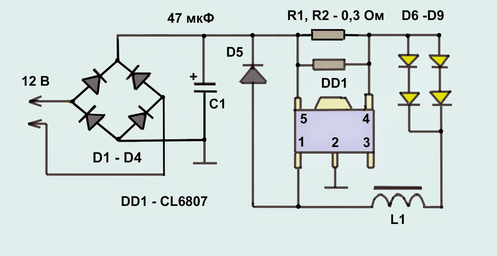
The diode bridge (D 1-D 4) on the lamp terminals makes it universal, which allows you to connect to a direct voltage without worrying about polarity reversal, in addition, it makes it possible to use the lamp with a low-voltage alternating voltage source with an interval from 6 to 20 volts (for constant with an interval from 8 to 30 volts).
The converter (chip CL 6807, R 1, R 2, L1, D 5) is responsible for such a large voltage spread. Its task is to limit the current as the voltage increases. Unlike the current limiting resistor, this converter has high efficiency= 95 percent, it also saves energy and, without releasing excess heat, occupies less space than a resistor.
The LEDs themselves are D6 - D9.
Everything seems fine, but lamps fail. The main reason is low-quality LEDs (more precisely, poor-quality welding of the semiconductor crystal to the desoldering taps). In this scheme, the shutdown will be in pairs; the lamp will first flash signals. I find the faulty LED by connecting one by one with a 3-volt structure (Fig. 4) to each LED of the disconnected lamp. Thus, out of two lamps, you can restore one, leaving spare parts for better times (by the way, beautiful radiators for transistors).
But what if you couldn't fix the lamp? Don't be upset. You can make a lot of different crafts from a broken lamp.
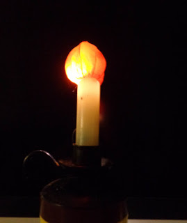 |
| Photo 5 Come see the light. |
The circuit of a 220 V LED lamp allows you not only to understand the operating principle of this device, but also to make it yourself. Attempts to make E27 type light bulbs on your own are due to the fact that it is not always possible to purchase a lighting device with the necessary characteristics. And just those who like to “tinker” with electronics are not averse to trying something new.
- Important nuances
- Schemes
- With diode bridge
- LEDs
- Resistor
- With diode bridge
Important nuances
The ballast circuit and the LED lamp circuit itself is a point of interest to many. We often ask questions about whether it is possible to make an LED light bulb yourself. The answer is unequivocal - yes.
Such a device can be made by hand. There are many systems according to which LED lighting operates on alternating current rated at 220 Volts. Moreover, all of them, together with the ballast circuit, are designed to solve three main problems.
- Convert 220V alternating current into pulsating current;
- Level out the pulsating current, making it constant;
- Achieve current levels of 12 Volts.
If you want to assemble a device with your own hands, powered by a regular 220 Volt network, you will have to deal with some basic problems to connect.
- Where to place the circuits and the LED-based device itself. After all, diodes will need their own place.
- How can you isolate an LED lighting device?
- How to ensure the necessary heat exchange for connecting a lamp.
Of course, you can safely purchase the popular e27 LED lamp. The E27 diode device is one of the most popular on the market; it works perfectly from a regular household network of 220 Volts. But this is too simple and not interesting for many.
Schemes
To assemble a circuit and get an LED device based on it for lighting a house using a 220-volt power supply, you will need:
- Equalize alternating current;
- Achieve the required power parameters;
- Provide the necessary resistance.
All this can be done in two ways. There are two main variations.
- Circuit based on a diode bridge.
- A resistor circuit where a specific number of LEDs are used.
They are quite simple, so the device can be assembled without any problems. Let's look at the schemes themselves and evaluate their advantages.
With diode bridge
- The diode bridge design includes 4 multi-directional LEDs;
- The task of the diode bridge is to make a pulsating current from a sinusoidal alternating current;
- Half-waves are conducted through 2 diodes, due to which the minus loses its polarity;
- In the circuit, it is necessary to connect a capacitor to the plus side on the side of the AC source in front of the diode bridge;
- Before the minus, a resistance with a nominal value of 100 Ohms is installed;
- The parallel bridge, behind it, will need to attach another capacitor. It will smooth out voltage surges;
- With basic skills in working with a soldering iron, assembling such a circuit will not be difficult for a novice craftsman.
LEDs
- The LED board can be used as a standard one, borrowed from a non-functioning lamp;
- Before assembly, be sure to check each element for functionality. To do this, use a 12 Volt battery;
- If there are non-working components, their contacts need to be unsoldered and new ones installed;
- Pay special attention to the cathode and anode legs. They should be connected in series;
- If you are simply replacing several parts of an old lamp, it is enough to replace non-working elements with functioning ones by installing them in their old places;
- If you decide to assemble the device yourself, remember an important rule - LED lamps are connected in series in groups of 10, after which the circuits should be connected in parallel.
As a result, your diagram should look like this.
- 10 LEDs are in one row. Then the legs of the anode and cathode are soldered so that there are 9 connections and 1 tail along the edges, which are in a free position.
- All resulting circuits are connected to wires. The ends of the cathode go to one, and the ends of the anode go to the other.
- Don't forget that the cathode is positive and connected to the negative. The anode is negative and must be connected to positive.
- Make sure that the ends soldered together in the diagram do not touch other ends. If such a situation happens, the circuit will burn out and a short circuit will occur.
Resistor
The electronic ballast circuit can provide the required operating power LED lamps, powered by 220V.
Another and enough simple circuit creating an LED device for power supply from 220 Volts is intended for those who want to do everything with their own hands. Creating ballast and connecting here is not difficult, so a relatively newbie in the field of electronics can handle such a task.
- The resistor circuit for LEDs consists of a pair of 12K resistors and a pair of chains;
- The chains consist of the same number of LED elements;
- LED elements are soldered in series and have different directions;
- On the R1 side, one strip of LED elements is soldered with the cathode, and the second strip with the anode;
- The second tap going to R2 is done in reverse;
- Due to this scheme, the glow of LED lamps is soft. This is due to the fact that the LED elements begin to burn one by one, so the pulsating flashes are practically invisible to the human eye;
- A similar LED device, powered by 220 Volts, can be used to illuminate a desktop or illuminate certain areas. Therefore, they can replace traditional lamps, obtaining light of similar efficiency or even a glow of higher quality;
- Practice shows that the resistor circuit of an LED device is most effective when using at least 20 LEDs. It is even preferable to use 40 elements;
- Due to such a number of LEDs and circuit features, you get high-quality lighting. There are absolutely no problems with assembling the circuit, everything is very simple;
- The only nuances of a circuit with 20-40 LEDs is that soldering must be done very carefully so as not to damage adjacent contacts. Plus, putting it all together into a single compact body is another challenge.
The possibilities of LEDs are endless. Their use is becoming widespread. At the same time, working with LEDs does not pose any difficulties.
Nowadays, the issue of energy saving arises more and more often. To solve this issue, many manufacturers produce energy saving lamps(fluorescent), having a base similar to that of standard 220 volt incandescent lamps.
The electricity consumption of this type of electric lamps is undoubtedly much less than that of simple 220-volt incandescent lamps. In turn, their designated service life is approximately 5000 hours, that is, approximately 5 times longer than the service life of a conventional lamp.
But with all the advantages, this electric lamp also has a drawback - the high price. These lamps use a special electronic ballast, but although it breaks very rarely, the filaments of this electric lamp burn out quite often, often without even working out the declared service life.
But now super-bright LEDs are being produced, which in turn can be used to make a homemade LED lamp with your own hands. The service life of current LEDs reaches approximately 50,000 hours, which is almost 6 years of constant operation.
Described in this article DIY LED lamp 220V specially created for power supply from a 220 V power supply.
Description of a 220 volt power source for a homemade LED lamp
The electrical circuit is quite simple and does not require adjustment. A special feature of this lamp is the use of LEDs with a large radiation angle, resulting in an even and bright light. In turn, the advantages of this lamp include very low power consumption (about 2 W) and increased efficiency.
The main element electrical diagram are ultra-bright LEDs (25 pieces) of the white emission spectrum. In the role of HL1 - HL25, it is better to use LEDs with an emission angle of 160 degrees, for example, brand 5WW4SC. They can be replaced with others with a direct voltage of 3.2 to 3.7 volts and a current consumption of about 20 mA.
The LEDs are powered from a transformerless power module, which consists of a quenching capacitor C1, resistance R1, rectifier bridge VD1...VD4, smoothing capacitance C2 and limiting resistance R2.
The mains voltage of 220 volts is extinguished by a circuit of elements R1, C1, R2. Capacitance C1 must have a voltage of at least 250 V. Then the reduced voltage goes to the rectifier bridge, and then through the capacitive filter C2 the voltage goes to the series-connected HL1 - HL25. When using 37 LEDs in a circuit, it is possible to remove resistance R2.
This circuit provides the ability to protect LEDs from surges of increased voltage of 220 volts. It consists of an 80 mA fuse and (TVR05361 or FNR05361). When increasing mains voltage The varistor resistance drops sharply, causing the fuse to blow.