
In the manufacture of various electronic structures, LEDs are often used, for example, in display units or signaling equipment operation. Probably everyone has worked with conventional indicator LEDs, but not everyone uses a two-color LED with two terminals, because few novice electronics engineers know about it. Therefore, I will talk a little about it and naturally we will connect a two-color LED to a 220 V alternating voltage network, since for some reason unknown to me this topic is of increased interest.
And so, we know that a “regular” LED passes current only in one direction: when the plus is applied to the anode, and the minus of the power source is applied to the cathode. If you change the polarity of the voltage source, no current will flow.

A two-color LED with two terminals consists of two back-to-back diodes connected in a common housing. Moreover, the body, or, more precisely, the lens, has standard dimensions and also only two terminals.

A special feature is that each LED terminal serves as the anode of one LED and the cathode of the second.
If you apply a plus to one pin and a minus to the second pin of the power supply, then one LED will be locked, and the second will light up, for example, green.

When the polarity of the power supply is changed, the green LED will be locked, and the red LED will light up.
Two-color LEDs are available in the following color combinations:
- Red Green;
- blue yellow;
- green - amber;
- Red Yellow.
How to connect a two-color LED with two terminals to a 220 V network
Such an LED is convenient to use on alternating current, since there is no need to use a reverse diode. Therefore, to connect a two-color LED to 220 V AC voltage, it is enough to add only a current-limiting resistor.

It is necessary to immediately make an amendment here that the nominal voltage in the network, which is also the same in the outlet, starting from October 2015, is no longer the usual 220 V, but 230 V. These and other data are reflected in GOST 29433-2014. The same standard provides permissible deviations from the rated voltage value of 230 V:
— nominal value 230 V;
— maximum 253 V (+10%);
— minimum 207 V (-10%);
— minimum under load 198 V (-14%).
Based on these assumptions, it is necessary to calculate the resistance of the current-limiting resistor so that it does not overheat and sufficient current flows through the LED for it to glow normally with the maximum permissible voltage fluctuations in the network.
Calculation of a current-limiting resistor
Therefore, although the nominal current value is 20 mA, we will take the calculated current value of a two-color LED as 7 mA = 0.007 A. At this value, it glows normally, since the brightness of the LED is not directly proportional to the current flowing through it.
Let's determine the resistance of the current-limiting resistor at a rated voltage in the socket of 230 V:
R = U/I = 230 V / 0.007 A = 32857 Ohm.
From the standard range of resistor values we select 33 kOhm.
Now let's calculate the power dissipation of the resistor:
P = I 2 R = 0.007 2 ∙33000 = 1.62 W.
We accept a 2-watt resistor.
Let us recalculate for the case of the maximum permissible voltage at a given value of the resistor resistance:
I = U/R = 253 / 33000 = 0.0077 A = 7.7 mA.
P = I 2 R = 0.0077 2 ∙33000 = 1.96 W.
As you can see, when the voltage increases by an acceptable 10%, the current will also increase by 10%, however, the power dissipation of the resistor will not exceed 2 W, so it will not overheat.
When the voltage decreases by an acceptable amount, the current will also decrease. At the same time, the power dissipation of the resistor will also decrease.
Hence the conclusion: as an indicator of the presence of a mains voltage of 230 V, it is enough to just use a two-color LED with two terminals and a current-limiting resistor with a resistance of 33 kOhm with a dissipation power of 2 W.

Everyone is now familiar with LEDs. Modern technology is simply unthinkable without them. These are LED lights and lamps, indication of operating modes of various household appliances, backlighting of the screens of computer monitors, televisions and many other things that you can’t immediately remember. All of the listed devices contain visible light-emitting diodes of various colors: red, green, blue (RGB), yellow, white. Modern technologies make it possible to obtain almost any color.
In addition to visible LEDs, there are infrared and ultraviolet LEDs. The main area of application of such LEDs is automation and control devices. Enough to remember. If the first remote control models were used exclusively to control televisions, now they are used to control wall heaters, air conditioners, fans and even kitchen appliances, such as multicookers and bread makers.
So what is an LED?
In fact, it is not much different from the usual one - the same p-n junction, and the same basic property of one-way conductivity. As we studied the pn junction, it turned out that in addition to one-way conductivity, this very junction has several additional properties. During the evolution of semiconductor technology, these properties were studied, developed and improved.
The Soviet radiophysicist (1903 - 1942) made a great contribution to the development of semiconductors. In 1919, he entered the famous and still known Nizhny Novgorod Radio Laboratory, and from 1929 he worked at the Leningrad Institute of Physics and Technology. One of the scientist’s areas of activity was the study of the weak, barely noticeable glow of semiconductor crystals. It is on this effect that all modern LEDs work.
This faint glow occurs when current is passed through the pn junction in the forward direction. But now this phenomenon has been studied and improved so much that the brightness of some LEDs is such that you can simply go blind.
 The color range of LEDs is very wide, almost all the colors of the rainbow. But the color is not obtained by changing the color of the LED housing. This is achieved by adding dopant impurities to the pn junction. For example, the introduction of a small amount of phosphorus or aluminum produces colors of red and yellow hues, while gallium and indium emit light from green to blue. The LED housing can be transparent or matte; if the housing is colored, then it is simply a light filter that matches the color of the p-n junction.
Another way to obtain the desired color is to introduce a phosphor. A phosphor is a substance that produces visible light when exposed to other radiation, even infrared. A classic example of this is fluorescent lamps. In the case of LEDs, white color is obtained by adding a phosphor to a blue crystal.
To increase the emission intensity, almost all LEDs have a focusing lens. Often the end of a transparent body, which has a spherical shape, is used as a lens. In infrared LEDs, sometimes the lens appears opaque, smoky gray in color. Although recently infrared LEDs have been produced simply in a transparent case, these are the ones used in various remote control systems.

Bi-color LEDs
Also known to almost everyone. For example, a charger for a mobile phone: while charging is in progress, the indicator lights up red, and when charging is complete, it lights up green. This indication is possible thanks to the existence of two-color LEDs, which can be of different types. The first type is three-terminal LEDs. One package contains two LEDs, for example, green and red, as shown in Figure 1.

Figure 1. Bi-color LED connection diagram
The figure shows a fragment of a circuit with a two-color LED. In this case, a three-terminal LED with a common cathode is shown (sometimes with a common anode) and its connection to. In this case, you can turn on either one or the other LED, or both at once. For example, it will be red or green, and if two LEDs are turned on at once, it will turn out yellow. If you use PWM modulation to adjust the brightness of each LED, you can get several intermediate shades.
In this circuit, you should pay attention to the fact that limiting resistors are included separately for each LED, although it would seem that you can get by with just one by including it in the common output. But with this switching on, the brightness of the LEDs will change when one or two LEDs are turned on.
What voltage is needed for an LED? This question can be heard quite often, asked by those who are not familiar with the specifics of LED operation or simply by people who are very far from electricity. In this case, it is necessary to explain that the LED is a device controlled by current, not voltage. You can turn on the LED at least at 220V, but the current through it should not exceed the maximum permissible. This is achieved by connecting a ballast resistor in series with the LED.
But still, remembering the voltage, it should be noted that it also plays a big role, because LEDs have a high forward voltage. If for a conventional silicon diode this voltage is about 0.6...0.7V, then for an LED this threshold starts from two volts and above. Therefore, the LED cannot be lit with a voltage of 1.5V.
But with this connection, meaning 220V, we should not forget that the reverse voltage of the LED is quite small, no more than a few tens of volts. Therefore, special measures are taken to protect the LED from high reverse voltage. The easiest way is to counter-connect a protective diode in parallel, which may also not be particularly high-voltage, for example KD521. Under the influence of alternating voltage, the diodes open alternately, thereby protecting each other from high reverse voltage. The circuit diagram for connecting the protective diode is shown in Figure 2.

Figure 2. Connection diagram parallel to the LED protective diode
Two-color LEDs are also available in a package with two terminals. In this case, the color of the glow changes when the direction of the current changes. A classic example is the indication of the direction of rotation of a DC motor. It should not be forgotten that a limiting resistor must be connected in series with the LED.
Recently, a limiting resistor is simply built into the LED, and then, for example, on the price tags in the store they simply write that this LED is rated at 12V. The flashing LEDs are also marked by voltage: 3V, 6V, 12V. There is a microcontroller inside these LEDs (you can even see it through the transparent case), so any attempts to change the blinking frequency do not produce results. With this marking, you can turn on the LED directly to the power supply at the specified voltage.
Developments of Japanese radio amateurs
It turns out that amateur radio is practiced not only in the countries of the former USSR, but also in such an “electronic country” as Japan. Of course, even an ordinary Japanese radio amateur is unable to create very complex devices, but individual circuit solutions deserve attention. You never know in what scheme these solutions might be useful.
Here is an overview of relatively simple devices that use LEDs. In most cases, control is carried out from microcontrollers, and there is no escape from this. Even for a simple circuit, it is easier to write a short program and solder the controller in a DIP-8 package than to solder several microcircuits, capacitors and transistors. Another attractive thing about this is that some microcontrollers can operate without any attached parts at all.
Bi-color LED control circuit
An interesting scheme for controlling a powerful two-color LED is offered by Japanese radio amateurs. More precisely, it uses two powerful LEDs with a current of up to 1A. But, we must assume that there are also powerful two-color LEDs. The diagram is shown in Figure 3.

Figure 3. Control circuit for a powerful two-color LED
The TA7291P chip is designed to control low-power DC motors. It provides several modes, namely: forward rotation, reverse rotation, stop and braking. The output stage of the microcircuit is assembled using a bridge circuit, which allows you to perform all of the above operations. But it was worth applying some imagination and, lo and behold, the microcircuit has a new profession.
The logic of the microcircuit is quite simple. As can be seen in Figure 3, the microcircuit has 2 inputs (IN1, IN2) and two outputs (OUT1, OUT2), to which two powerful LEDs are connected. When the logic levels at inputs 1 and 2 are the same (00 or 11 makes no difference), then the output potentials are equal, both LEDs are off.
At different logical levels at the inputs, the microcircuit operates as follows. If one of the inputs, for example, IN1, has a low logical level, then the output OUT1 is connected to the common wire. The cathode of LED HL2 is also connected to the common wire through resistor R2. The voltage at the OUT2 output (if there is a logical one at the IN2 input) in this case depends on the voltage at the V_ref input, which allows you to adjust the brightness of the HL2 LED.
In this case, the voltage V_ref is obtained from PWM pulses from the microcontroller using the integrating chain R1C1, which regulates the brightness of the LED connected to the output. The microcontroller also controls the inputs IN1 and IN2, which allows you to obtain a wide variety of shades of light and LED control algorithms. The resistance of resistor R2 is calculated based on the maximum permissible current of the LEDs. How to do this will be described below.
Figure 4 shows the internal structure of the TA7291P chip and its block diagram. The diagram is taken directly from the datasheet, so it shows an electric motor as a load.

Figure 4.
Using the block diagram, it is easy to trace the current paths through the load and methods of controlling the output transistors. The transistors are switched on in pairs, diagonally: (upper left + lower right) or (upper right + lower left), which allows you to change the direction and speed of the engine. In our case, light one of the LEDs and control its brightness.
The lower transistors are controlled by signals IN1, IN2 and are simply designed to turn the bridge diagonals on and off. The upper transistors are controlled by the Vref signal, they regulate the output current. The control circuit, shown simply as a square, also contains a protection circuit against short circuits and other unforeseen circumstances.
Ohm's law, as always, will help in these calculations. Let the initial data for the calculation be the following: supply voltage (U) 12V, current through the LED (I_HL) 10mA, the LED is connected to a voltage source without any transistors or microcircuits as a power-on indicator. The voltage drop across the LED (U_HL) is 2V.
Then it is quite obvious that the limiting resistor will receive voltage (U-U_HL), - two volts were “eaten” by the LED itself. Then the resistance of the limiting resistor will be
R_o = (U-U_HL) / I_HL = (12 - 2) / 0.010 = 1000(Ω) or 1KOhm.
Don't forget about the SI system: voltage in volts, current in amperes, result in Ohms. If the LED is turned on by a transistor, then in the first bracket the voltage of the collector-emitter section of the open transistor should be subtracted from the supply voltage. But, as a rule, no one ever does this; accuracy down to hundredths of a percent is not needed here, and it will not work due to the scattering of the parameters of the parts. All calculations in electronic circuits give approximate results, the rest has to be achieved by debugging and tuning.
Tri-color LEDs
In addition to two-color ones, recently they have become widespread. Their main purpose is decorative lighting on stages, at parties, at New Year's celebrations or at discos. Such LEDs have a body with four terminals, one of which is a common anode or cathode, depending on the specific model.
But one or two LEDs, even three-color ones, are of little use, so you have to combine them into garlands, and to control the garlands use all kinds of control devices, which are most often called controllers.
Assembling garlands of individual LEDs is boring and uninteresting. Therefore, in recent years, the industry has begun to produce strips based on three-color (RGB) LEDs. If single-color tapes are produced for a voltage of 12V, then the operating voltage of three-color tapes is often 24V.
LED strips are marked by voltage because they already contain limiting resistors, so they can be connected directly to a voltage source. Sources for are sold in the same place as the tapes.
Special controllers are used to control three-color LEDs and strips to create various lighting effects. With their help, it is possible to simply switch LEDs, adjust brightness, create various dynamic effects, as well as draw patterns and even paintings. The creation of such controllers attracts many radio amateurs, naturally those who know how to write programs for microcontrollers.
Using a three-color LED, you can get almost any color, because the color on a TV screen is also obtained by mixing only three colors. Here it is appropriate to recall another development of Japanese radio amateurs. Its circuit diagram is shown in Figure 5.

Figure 5. Three-color LED connection diagram
A powerful 1W three-color LED contains three emitters. With the resistor values indicated in the diagram, the glow color is white. By selecting resistor values, a slight change in shade is possible: from cold white to warm white. In the author's design, the lamp is designed to illuminate the interior of a car. Surely they (the Japanese) should be sad! In order not to worry about maintaining polarity, a diode bridge is provided at the input of the device. The device is mounted on a breadboard and is shown in Figure 6.

Figure 6. Development board
The next development of Japanese radio amateurs is also of an automotive nature. This device for illuminating the license plate, of course, with white LEDs is shown in Figure 7.

Figure 7. Diagram of a device for illuminating the license plate on white LEDs
The design uses 6 powerful, ultra-bright LEDs with a maximum current of 35mA and a luminous flux of 4lm. To increase the reliability of the LEDs, the current through them is limited to 27 mA using a voltage stabilizer chip connected as a current stabilizer circuit.
LEDs EL1...EL3, resistor R1, together with microcircuit DA1 form a current stabilizer. A stable current through resistor R1 maintains a voltage drop across it of 1.25V. The second group of LEDs is connected to the stabilizer through exactly the same resistor R2, so the current through the group of LEDs EL4...EL6 will also be stabilized at the same level.
Figure 8 shows a converter circuit for powering a white LED from one galvanic cell with a voltage of 1.5V, which is clearly not enough to light the LED. The converter circuit is very simple and is controlled by a microcontroller. In fact, the microcontroller is a pulse frequency of about 40KHz. To increase the load capacity, the microcontroller pins are connected in pairs in parallel.

Figure 8.
The scheme works as follows. When pins PB1, PB2 are low, outputs PB0, PB4 are high. At this time, capacitors C1, C2 are charged to approximately 1.4V through diodes VD1, VD2. When the state of the controller outputs changes to the opposite, the sum of the voltages of two charged capacitors plus the voltage of the battery will be applied to the LED. Thus, almost 4.5V will be applied to the LED in the forward direction, which is quite enough to light the LED.
Such a converter can be assembled without a microcontroller, simply on a logic chip. Such a diagram is shown in Figure 9.
Figure 9.
A square wave generator is assembled on element DD1.1, the frequency of which is determined by the ratings R1, C1. It is at this frequency that the LED will flash.
When the output of element DD1.1 is high, the output of DD1.2 is naturally high. At this time, capacitor C2 is charged through diode VD1 from the power source. The charging path is as follows: plus the power supply - DD1.1 - C2 - VD1 - DD1.2 - minus the power supply. At this time, only battery voltage is applied to the white LED, which is not enough to light the LED.
When the level at the output of element DD1.1 becomes low, a high level appears at the output of DD1.2, which leads to the blocking of diode VD1. Therefore, the voltage on capacitor C2 is summed with the battery voltage and this sum is applied to resistor R1 and LED HL1. This amount of voltage is quite enough to turn on the HL1 LED. Then the cycle repeats.
How to test an LED
If the LED is new, then everything is simple: the terminal that is slightly longer is the positive one or the anode. It is this that must be connected to the positive of the power source, naturally not forgetting about the limiting resistor. But in some cases, for example, the LED was soldered from an old board and its leads are the same length, a continuity test is required.
Multimeters behave somewhat incomprehensibly in such a situation. For example, a DT838 multimeter in semiconductor testing mode can simply light up the LED being tested slightly, but the indicator shows a break.
Therefore, in some cases, it is better to check LEDs by connecting them through a limiting resistor to a power source, as shown in Figure 10. The resistor value is 200...500 Ohm.

Figure 10. LED test circuit
Figure 11. Sequence of LEDs
Calculating the resistance of the limiting resistor is easy. To do this, you need to add up the forward voltage on all LEDs, subtract it from the power source voltage, and divide the resulting remainder by the given current.
R = (U - (U_HL_1 + U_HL_2 + U_HL_3)) / I
Let's assume that the power supply voltage is 12V and the voltage drop across the LEDs is 2V, 2.5V and 1.8V. Even if the LEDs are taken from the same box, there can still be such a scatter!
According to the conditions of the problem, the current is set to 20 mA. All that remains is to substitute all the values into the formula and learn the answer.
R = (12- (2 + 2.5 + 1.8)) / 0.02 = 285Ω

Figure 12. Parallel connection of LEDs
On the left fragment, all three LEDs are connected through one current-limiting resistor. But why is this scheme crossed out, what are its shortcomings?
This is where the variation in LED parameters comes into play. The greatest current will flow through the LED that has a smaller voltage drop, that is, a smaller internal resistance. Therefore, with this switching on, it will not be possible to achieve a uniform glow of the LEDs. Therefore, the correct circuit should be considered the circuit shown in Figure 12 on the right.
Multicolor LEDs appeared after two-color “red-green” ones, when advances in technology made it possible to place blue emitters on their crystals. The invention of “blue” and “white” LEDs has completely closed the RGB circle: now it has become possible to display any color of the rainbow in the visible wavelength range 450...680 nm with any saturation.
There are several ways to produce white “LED” light (precisely “light”, since white “color” does not exist in nature).
The first method is to apply a yellow phosphor to the inner surface of the “blue” LED lens. “Blue” plus “yellow” add up to a tone close to white. This is how the world's first “white” LEDs were created.
The second method is to apply three layers of phosphor, blue, green and red, to the surface of a light emitter operating in the ultraviolet range of 300...400 nm (invisible radiation). Mixing of spectral components occurs, as in a fluorescent lamp.
The third method is LCD television screen technology. On one substrate, “red”, “blue” and “green” emitters are placed close to each other (like three guns in a picture tube). Color proportions are set by different currents through each emitter. The final mixing of the paints until a white shade is obtained is carried out by the light-diffusing lens of the housing.
The fourth method is implemented in so-called “quantum” LEDs, in which red, green and blue “quantum” dots or, in other words, luminescent nanocrystals are applied to a common semiconductor wafer. This is a promising energy-saving direction, but still exotic.
Today, multicolor LEDs of the third type, having taps from three emitters, are of interest to amateur practice. They can be used to create full-color information display devices, for example, in the form of LED television screens. One pixel of such a screen can shine in blue (470 nm), green (526 nm) or red (630 nm). In total, this allows you to get almost the same number of shades as in computer monitors.
Multicolor LEDs come in four- and eight-pin types. In the first case, there are three terminals for red (R), green (G) and blue (B) emitters, supplemented by a fourth terminal for a common cathode or anode. In the six-pin version, three completely autonomous RGB LEDs or two two-color pairs: “red-blue”, “green-blue” are placed in one housing. Eight-pin LEDs additionally have a “white” emitter.
Interesting point. It has been proven that most men do not accurately perceive colors in the red part of the spectrum. Mother Nature herself is to blame for this because of the OPNlLW gene located on the X chromosome. Men have one gene, but women have two copies of it, which mutually compensate for each other's defects. Manifestation in everyday life - women, as a rule, distinguish between raspberry, burgundy and scarlet shades well, and for many men such tones seem equally red... Therefore, when designing equipment, it is necessary to avoid “conflicting” colors and not force the user to look for the difference in small details.
In Fig. 2.17, a... and shows diagrams for connecting four- and six-pin multicolor LEDs to MK.
Rice. 2.17. Schemes for connecting multicolor LEDs to MK (beginning):
R3* co a) the current through each of the three emitters of red (R), green (G) and blue (B) is determined by resistors R2...R4 - no more than 20...25 mA for each line MK. Resistor R1 organizes negative current feedback. With its help, the overall brightness of the glow is reduced when three emitters are turned on simultaneously;
b) similar to Fig. 2.17, a, but for the HL1 LED with a common anode and with an active LOW level at the MK outputs;
c) three-channel PWM control provides a full RGB color gamut. The resistances of resistors R1...R3 are selected within a wide range according to the subjective color sensation of white balance with three emitters turned on. For a uniform transition from one color to another, a nonlinear PWM control law is needed. The average current through one MK line during one PWM period should not exceed 20...25 mA with a pulse current of no more than 40 mA;
d) similar to Fig. 2.17, v, but for the HL1 LED with a common anode and with an active LOW level of PWM signals;
e) the HL1 LED contains three completely autonomous emitters with separate leads from the housing, which gives a certain freedom of action. For example, you can connect indicators according to a circuit with both a common anode and a common cathode; ABOUT

About Fig. 2.17. Connection diagrams for multicolor LEDs to MK (end):
f) simulator of a multicolor LED. Three conventional LEDs HL1..HL3 of red, green and blue colors are structurally placed in one common light-diffusing housing. To better imitate the original, you can use small-sized SMD LEDs;
g) powerful multicolor LEDs cannot be connected directly to the MK, due to the low load capacity of the ports. Transistor switches with a permissible current of at least 500 mA for “one-watt” LEDs (350 mA) and at least 1 A for “three-watt” LEDs (700 mA) are required. It is recommended to power the MK and the HL1 LED from different sources through a voltage stabilizer, so that interference from switching a powerful load does not interfere with the operation of the program. If the supply voltage of the HL1 LED is high, the resistance of resistors R4...R6 and their power should be increased. The LED itself must be installed on a radiator 5 ... 10 cm 2;
h) the six-pin LED HL1 is controlled from four MK lines. By combining LOW/HIGH levels different color shades can be achieved. Ideally, a mixture of blue and green produces blue, and a mixture of red and green produces yellow;
i) the HL1 output LED allows you not only to mix the colors red (R), green (G), blue (B), but also to adjust their saturation by adding a white component (W). Each of the HL1 LED emitters is designed for an operating current of 350 mA, so it is necessary to provide measures for effective heat removal with a metal radiator.
Multicolor LEDs, or RGB as they are also called, are used to display and create dynamically changing color lighting. In fact, there is nothing special about them, let's figure out how they work and what RGB LEDs are.
Internal organization
In fact, an RGB LED is three single-color crystals combined in one housing. The name RGB stands for Red - red, Green - green, Blue - blue, according to the colors that each crystal emits.
These three colors are basic, and by mixing them any color is formed; this technology has long been used in television and photography. In the picture above, you can see the glow of each crystal individually.

In this picture you see the principle of mixing colors to obtain all shades.
Crystals in RGB LEDs can be connected according to the following scheme:
With common anode;

With a common cathode;

Not connected.
In the first two options, you will see that the LED has 4 pins:

Or 6 conclusions in the latter case:

You can see in the photo there are three crystals clearly visible under the lens.
Special mounting pads are sold for such LEDs, and the pin assignments are even indicated on them.

RGBW LEDs cannot be ignored; their difference is that in their housing there is another crystal emitting white light.

Naturally, we could not do without strips with such LEDs.

This picture shows a strip with RGB LEDs, assembled according to a circuit with a common anode; the glow intensity is adjusted by controlling the “-” (minus) of the power source.
To change the color of an RGB tape, special RGB controllers are used - devices for switching the voltage supplied to the tape.
Here is the RGB SMD5050 pinout:

And the tapes, there are no special features of working with RGB tapes, everything remains the same as with single-color models.

There are also connectors for connecting LED strips without soldering.

Here is the pinout of a 5 mm RGB LED:

How the color of the glow changes
Color adjustment is carried out by adjusting the brightness of the radiation from each of the crystals. We have already looked at.
An RGB controller for tape works on the same principle; it contains a microprocessor that controls the negative terminal of the power source - connects and disconnects it from the circuit of the corresponding color. Usually a remote control is included with the controller. Controllers come in different capacities, their size depends on this, starting from such a miniature one.

Yes, such a powerful device in a case the size of a power supply.

They are connected to the tape according to the following scheme:
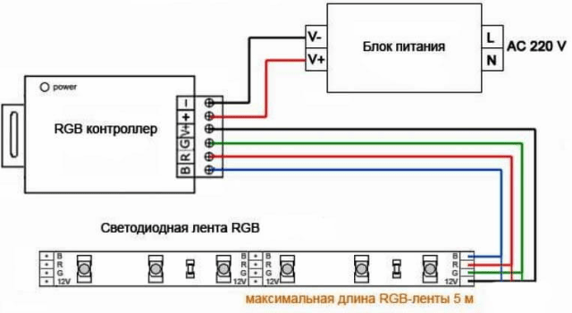
Since the cross-section of the tracks on the tape does not allow connecting the next section of the tape in series with it, if the length of the first exceeds 5 m, you need to connect the second section with wires directly from the RGB controller.
But you can get out of the situation and not pull additional 4 wires 5 meters from the controller and use an RGB amplifier. For it to work, you need to stretch only 2 wires (plus and minus 12V) or power another power supply from the nearest 220V source, as well as 4 “information” wires from the previous segment (R, G and B) they are needed to receive commands from the controller, so that the entire structure glows equally.

And the next segment is already connected to the amplifier, i.e. it uses the signal from the previous piece of tape. That is, you can power the tape from the amplifier, which will be located directly next to it, thereby saving money and time on laying wires from the primary RGB controller.
We adjust RGB-led with our own hands
So, there are two options for controlling RGB LEDs:
Here is a version of the circuit without using Arduino and other microcontrollers, using three CAT4101 drivers capable of delivering current up to 1A.

However, now controllers are quite cheap and if you need to regulate the LED strip, it is better to purchase a ready-made option. Circuits with Arduino are much simpler, especially since you can write a sketch with which you will either manually set the color, or the selection of colors will be automatic in accordance with a given algorithm.
Conclusion
RGB LEDs make it possible to create interesting lighting effects; they are used in interior design, as backlighting for household appliances, and for the effect of expanding the TV screen. There are no special differences when working with them from conventional LEDs.