Page 13 of 35
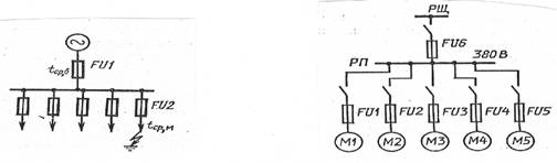
Various devices are used at substations; according to their purpose, they can be divided into the following groups: switching devices, which are designed to turn on and off circuits with voltages up to 1000 V and above 1000 V. In circuits up to 1000 V these include circuit breakers, switches, contactors, magnetic starters, air circuit breakers; in switchgear (RU) above 1000 V - switches and high-speed circuit breakers DC, disconnectors, short circuiters and separators;
protective devices - fuses and arresters;
devices for limiting short-circuit currents. - additional resistors, reactors;
measuring devices and instruments - current and voltage transformers, instruments for measuring currents, voltages, powers and other quantities;
equipment for protection, control, automation and increasing the efficiency of the electrical system.
Flexible and rigid busbars, power and control cables, and wires are used as live parts.
Switches for disconnecting circuits with voltages up to 1000 V: circuit breakers and switches are designed to turn on and off AC and DC circuits with voltages up to 660 V. They can be one-, two-, three- and four-pole. Knives and fixed contacts carry a rated current of up to 1000 A. Switches have additional contacts to which a second circuit is connected, and allow switching from one circuit to another. They are turned on and off manually.
Contactors and magnetic starters are the same switches, but they are controlled remotely. They are used when the circuit is frequently switched on and off by maintenance personnel.
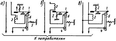
Magnetic starters (Fig. 35, a) are used to remotely turn on and off motors. The magnetic starter consists of a casing in which there is a three-pole switch 2, a thermal relay, a coil with a core 4, block contacts 1 and buttons for turning on the HF and turning off the KO.
Rice. 35. Low voltage switch circuits: a - magnetic starter; b - contactor
When you press the HF button, core 4 attracts armature 3 and movable contacts 2 close the power circuit. Disabling is carried out using the KO button; in this case, the coil is de-energized and the knives, under the influence of their own mass, break the power circuit. To protect against overload, a thermal relay is provided; it consists of a bimetallic element, contacts 5 and a heating element 6 connected to the power circuit. In case of overload, the thermal relay automatically turns off the circuit.
Contactors (Fig. 35, b) are used for remote starting and stopping of motors, turning on and off drives of high-voltage switches. When the circuit of the coil of the electromagnet 4 is closed, the armature 3 is attracted and the contacts 1 close the power circuit. Spring 7 accelerates the divergence of contacts 1 when disconnected. The contactors are equipped with arc-extinguishing chambers 8. From short-circuit currents. electrical circuits, in which circuit breakers, switches, magnetic starters and contactors are installed, are protected by fuses<с плавкими вставками.
Air circuit breakers are designed for quickly switching on and off circuits, protecting against short-circuit currents, as well as protecting receivers when the voltage and current decrease or increase and the direction of the current changes. Automatic switches are of maximum, minimum current and voltage, reacting accordingly to changes in these values, etc.
For overcurrent switches (Fig. 36, a), latch lever 1, under the action of spring 2, holds movable contact 6 in the on position. When the current exceeds the permissible value in coil 3, latch 1 is released, movable contact 6 rotates around axis 4 and opens the circuit. In the minimum current switch (Fig. 36, b), when the current in coil 3 becomes lower than that required to keep the armature in the attracted position, the movable contact 6 rotates under the action of spring 5 and also opens the circuit.
Rice. 36. Schematic diagrams of air circuit breakers of maximum (a) and minimum (b) currents, maximum voltage (c)
Maximum and minimum voltage circuit breakers differ from those considered in that the coils 3 in them are connected in parallel to the protected circuit. Circuit breakers are switched on manually or remotely and are equipped with arc chutes. At substations, three-phase circuit breakers are installed on the secondary side of auxiliary transformers at voltages up to 660 V.
Fuses are installed to protect electrical circuits and devices from short-circuit currents. And. overloads The fuse consists of an easily melting metal insert reinforced in. case, and represents an artificially weakened section of the protected circuit. When the current in the circuit increases to a level that is dangerous for wires and devices, the fuse-link melts (burns out) and disconnects the protected circuit from the power source.
Fuses are installed in circuits up to 1000 V, their inserts are made of tin, zinc and copper, and above 1000 V - of copper and silver. Fuse links for different rated currents can be inserted into the fuse body.
Fuses for voltages up to 1000 V are manufactured for rated currents of fuse links from 6 to 1000 A, and fuses for voltages above 1000 V are made for currents up to 400 A. Fuses are characterized by rated voltage and current, and fuses for voltages above 1000 V are also characterized. the maximum switchable current that the fuse can switch off without being damaged. Selective action of fuses is ensured only in radial open-loop networks.
Switches for voltages over 1000 V are used to turn on and off circuits under load and automatically turn off during a short circuit. and overloads. In AC installations, oil, air, electromagnetic, vacuum and SF6 circuit breakers are used, and in DC installations, high-speed switches are used. Switches must have a certain breaking capacity and the shortest possible shutdown time. There are circuit breakers for voltages up to 750 kV with a breaking power of up to 35,000 MB-A. The shutdown time is 0.03-0.08 s, and for high-speed switches it is thousandths of a second.
Disabling the power circuit is accompanied by the appearance of an electric arc between the contacts of the disconnecting device. An arc having a temperature of 5,000-10,000°C must be extinguished as soon as possible, especially during a short circuit. The conditions for extinguishing the arc in alternating current circuits are facilitated by the fact that the current passes through a zero value every half cycle and the arc goes out at this moment. In this case, intense deionization and a rapid increase in the electrical strength of the arc gap are observed.
The AC switch must prevent the arc from re-igniting after it has gone out when the current passes through zero. This is achieved by rapid divergence of contacts and the use of special arc extinguishing devices. The arc extinguishing process for previously produced switches lasted 10-15 periods (0.1-0.15 s), while for modern ones it lasted only 1-3 half-cycles. Significant overvoltages do not occur when the arc is extinguished in alternating current circuits, since when the current passes through zero, the magnetic flux disappears.
The conditions for arc extinction in DC circuits are much more severe and are associated with the occurrence of large switching overvoltages. To extinguish the arc, it is necessary to continuously reduce the number of ionized particles in the arc, and, consequently, the current in the circuit.
If there is inductance in the circuit and the current decreases when switched off, emission is induced in it. d.s., which is summed with the main voltage, resulting in overvoltage. The more intense the deionization of the arc, the greater the rate of change of current and
overvoltages that are dangerous for the insulation of electrical equipment. Therefore, AC switches with high arc-extinguishing capacity cannot be used in high-voltage direct current installations. In these circuits, switches are installed with arc extinguishing in air, at which overvoltages do not exceed three or four times the rated voltage of the installation.
To extinguish the arc in high-speed circuit breakers, magnetic blast and arc extinguishing chambers are used. It is impossible to use oil switches in DC installations, since the high deionizing ability of the oil leads to a rapid drop in the current to zero. 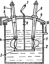
Rice. 37. Multi-volume oil circuit breaker without arc extinguishing devices
Oil switches can be with a large volume of oil (tank) or with a small volume (pot). In the first, oil is used to extinguish the arc and isolate live parts from each other and from the grounded tank, in the second - only as a medium for extinguishing the arc.
Drives are used to control switches.
Let's consider a multi-volume large-scale switch with two breaks per phase without arc extinguishing devices (Fig. 37). The metal tank 1 is closed on top with a lid 9 and filled to a certain level with mineral oil.
Fixed contacts 4 are mounted on bushings 6, movable contacts 2 are mounted on a traverse 3, which is connected to the drive mechanism of the switch and can move in the vertical direction. Switching on is carried out by the drive when shaft 7 rotates. Switching off occurs under the action of spring 8 and the traverse's own weight when the drive latch is released. When the switch is turned off, contacts 2 and 4 diverge and two successive arcs arise between them. Under the influence of the high temperature of the arc, the oil evaporates and decomposes, forming gas bubbles. The gas bubble consists of 70% hydrogen, the heat capacity of which is 7 times greater than the heat capacity of air, and 30% other gases. Deionization occurs due to the formation of a hydrogen environment and high pressure of the gas bubble.
The buffer space plays an important role (20-30% of the volume of the tank not filled with oil), it allows the oil to rise as it expands upward, as a result of which the pressure on the walls and bottom of the tank decreases. If this space is not enough, the tank may be destroyed. When the oil level is low, the gas bubble, not having time to cool, combines with oxygen in the air and can cause an explosion. To control the oil level in the tank, oil indicator glass 10 is used. The buffer space of the switch is connected to the atmosphere by tube 5. Multi-volume switches for voltages of 35 kV and above have a tank for each phase.
To speed up the extinguishing of the arc and increase the shutdown power of oil switches, special arc extinguishing devices are used, which create an intense gas blast with a small divergence of the contacts.
For MKP-110 m circuit breakers (oil-type, with an arc-extinguishing chamber, substation voltage 110 kV), arc-extinguishing devices (two per phase) are mounted on the rods of the fixed contacts of the switch and represent a chamber with a fourfold current break. The arc formed when the contacts open creates a high gas pressure in the chamber, under the influence of which the oil, together with the arc, enters the switch tank through the holes. A transverse blast is created in the extinguishing chamber and the electric arc goes out within two to three half-cycles.
The disadvantages of multi-volume circuit breakers are their large weight and size, explosion and fire hazard, and a large amount of oil in them (8.5-9 tons in 110 kV circuit breakers; 45-48 tons in 220 kV circuit breakers and 88 tons in manual transmission circuit breakers). 500 to 500 kV).
In installations with a voltage of 6-110 kV, oil switches with a small volume of oil are used. They are more compact, less fire and explosion hazardous and allow the use of complete switchgear structures, conveniently built into the switchgear chamber, KSO, etc. The mass of oil in circuit breakers at 10 kV is 4.5 kg, and at 110 kV - 600 kg.
The industry produces more advanced low-volume oil switches of the VMP-10, VMP-10K types with spring and electromagnetic drives.
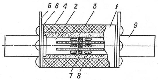
Hanging switch VMP-10K (for complete switchgear) (Fig. 38), its breaking capacity is 350 MB-A, t/H = 10 kV, current = 630-M 500 A. It consists of three phases - tanks 1 made of glass epoxy resin , mounted on support insulators 2, and installed on a steel frame 3, an insulated rod 4 is connected to the switch drive by a shaft 7. To soften shocks when turning on and off, buffers are provided - spring and oil 5. There are insulating partitions 8 between the phases; a bolt is used to ground the frame 6. When the switch is turned off, movable contact rods pass through the tank into an extinguishing chamber located at the bottom of the oil tank. An electric arc occurs and gases are formed, which, together with oil under pressure, rush into the transverse channels and extinguish the arc.
Rice. 38. Oil switch VMP-10K
At AC substations in 27.5 kV circuits supplying the contact network, single-phase oil switches VMK-25 (Fig. 39) of a 1000 A column type with a small amount of oil (25 kg) are installed. Response time 0.1 s, breaking power 300 MB-A.
In electrical installations, air circuit breakers are used, in which the electric arc is extinguished in a stream of compressed air coming from a compressor unit with a pressure of 0.8 to 2.2 MPa. Air circuit breakers are used in 330-750 kV networks.
Electromagnetic switches (EMS) are intended for 6-10 kV networks with a rated current of up to
3200 A in switchgear located indoors. The switch has working and arcing contacts in the open air. The principle of arc extinguishing is based on the interaction of the magnetic field and the arc current, which moves at a speed of 30 m/s inside the arc extinguishing chamber, where it is stretched, deionized and goes out after 0.01-0.02 s. The electromagnetic switch is explosion- and fire-proof, allows a large number of switchings without burning the contacts, and is installed in subway substations.
The industry produces SF6 and vacuum circuit breakers. They are small in size, their shutdown time is 0.01 s, and they are fire and explosion proof.
In SF6 circuit breakers, sulfur hexafluoride F6S is used as an insulating and arc-extinguishing medium. They are produced for voltages of 6-750 kV with a shutdown current of 50-60 kA. SF6 gas has an arc-extinguishing ability (100 times greater than that of air) and has 2-3 times greater electrical strength.
At AC traction substations, VEGO-27.5 gas-insulated switches are used in 27.5 kV switchgears (Fig. 40). The switches have a rated current of -1000 A, breaking power of 450 MB-A, gas pressure in the extinguishing chamber of 0.2-0.25 MPa.
Vacuum circuit breakers are designed for voltages up to 220 kV. They are installed in 6, 10 and 20 kV switchgear (Fig. 41). The switch is a glass sealed cylindrical body from which air has been evacuated with a pressure of 10-4 Pa. A fixed contact is mounted through the upper flange, and a movable contact is mounted through the lower flange with a seal. The moving contact travel is only 4 mm. When the contacts open, no arc is formed, since there is no ionizing medium. 97
Rice. 40. Switch with SF6 filling:
Rice. 39. Single-phase oil switch VMK-25:
1 - cap; 2 - exhaust pipe; 3 - sight glass; 4 - contact terminals; 5 - supporting porcelain column, inside of which there are fixed and movable contacts and an arc-extinguishing chamber; 6 - switch frame
At currents of 1000-1200 A, they allow 5-10 thousand short circuit trips. The shutdown time is 0.01 s. Vacuum circuit breakers are used at traction substations in automatic blocking networks, longitudinal overhead lines and in capacitive compensation installations. 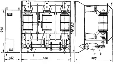
Rice. 41. Three-phase vacuum circuit breaker VVV-10/320:
1 - switch drive; 2 - switch shaft; 3 - movable insulator;
4 - bolt rod; 5 - switch chamber
Thyristor switches are designed for a voltage of 10 kV. With natural switching, they turn off the electrical circuit after half a cycle.
The choice of switches is carried out according to rated current, rated voltage, breaking power, dynamic and thermal resistance to short-circuit currents. and installation location.
Switch drives for voltages over 1000 V are designed to turn them on and off, as well as to hold them in the on position. Manual, load, spring, electromagnetic and pneumatic drives are used. All drives are made with free release, that is, with a mechanism that ensures automatic shutdown of the circuit breaker when it is switched on.
Electromagnetic drives are the main ones for remote control. They are simple, reliable in operation, cheap, but they require a direct current source with a voltage of 110 or 220 V (with alternating current, the dimensions of the electromagnets are larger and the design of the drives is more complex). There are drives of types PS (solenoid drive) and PE-11 (electromagnetic).
Disconnectors are designed for disconnecting and connecting electrical circuits with voltages above 1000 V without load. They do not have arc extinguishing devices. To carry out equipment repairs, first turn off the circuit breaker and then the disconnectors. When putting equipment into operation, on the contrary, first turn on the disconnectors and then turn on the switch.
Disconnectors allow you to turn on and off circuits of measuring voltage transformers, circuits with no-load current of power transformers, as well as charging currents of cable and overhead power lines of short length with voltages up to 110 kV. They are made for indoor and outdoor installation, with and without grounding blades. According to their purpose, they can be linear, busbar, or sectional.
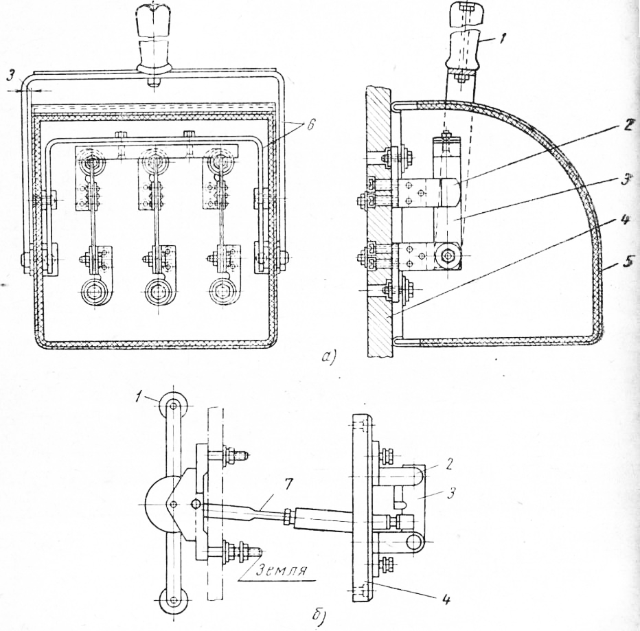
For a chopping type disconnector (for internal installation), movable contacts 1 (Fig. 42) and fixed contacts 2 are made of copper and are located on support insulators 3, which are mounted on frame 4. Lever 6, located on shaft 5, serves to turn on and off the movable contacts using insulating rods 7.
The disconnectors are controlled using manual, electric motor or pneumatic drives. To prevent incorrect operations by maintenance personnel when working with disconnectors, mechanical interlocks and electromagnetic locks are installed that do not allow the disconnector to be turned off until the switch is turned off. 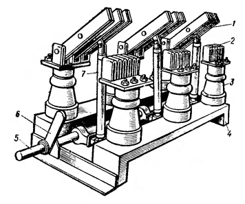
Rice. 42. Three-phase chop-type disconnector 6 kV
The selection of disconnectors is carried out according to rated current and voltage, type of installation, number of poles, design and type of drives.
The selected disconnector is checked for dynamic and thermal resistance to short-circuit currents.
Short circuiters and separators are installed at intermediate and dead-end substations with a voltage of 35-220 kV that do not have switches on the high voltage side (see paragraph 2). Their use reduces the cost of substations and simplifies their operation.
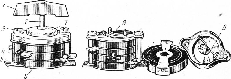
The short circuiter KZ-110 (Fig. 43) for a voltage of 110 kV is made in the form of a single-pole device. It consists of a column of insulators 6, a fixed contact 4, to which one of the phases 5 is connected, a tubular steel knife 3, to which a grounding bus 2 is connected, and a channel base 1. The angle of rotation of the knife is 60°. The short circuiter is controlled using a drive installed in the ShPK closet. Switching on occurs automatically when the transformer relay protection is triggered. 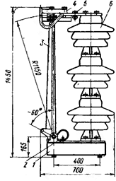
Rice. 43. Short circuiter type KZ-110
Switch off the short circuiter manually.
The OD-110 separator is a two-column three-phase disconnector equipped with an automatic drive; differs from the disconnector in speed. It consists of two insulators 1 (Fig. 44), on which movable contacts with a contact device 5 are mounted, a base 3, two cast iron bases 2 and disconnecting springs 4. The separator has a drive. Switching on and off is carried out by turning both insulators simultaneously using rods. The drive allows you to automatically turn off and turn on the separator.
Current transformers (CTs) are used in high and low voltage alternating current installations to power the windings of protection relays and measuring instruments.
Current transformers reliably isolate devices from high voltage (Fig. 45, a), ensure safe maintenance and allow the use of standard devices and relays. 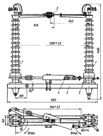
Rice. 44. Separator type OD-110\600
The rated current of the secondary winding of a CT is usually 5 A. According to the degree of measurement accuracy, CTs are divided into five classes: 0.2; 0.5; 1; 3; 10. 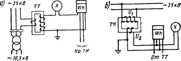
Rice. 45. Connection diagram of current (a) and voltage (b) transformers
For laboratory measurements, CTs of accuracy class 0.2 are used, for connecting meters for which cash payments are made - class 0.5, for connecting devices - class 1 and relay protections - classes 3 and 10.
The current windings of measuring instruments and relays have low resistance, so CTs operate normally in short-circuit mode. Opening the secondary winding when there is current in the primary circuit is unacceptable, since the transformer insulation may be damaged and high voltage will appear on the secondary winding.
When replacing a measuring device or relay, first short-circuit the secondary winding of the CT. According to their design, CTs are divided into coil, support, feed-through, and built-in; according to the number of turns of the primary winding - single-turn and multi-turn; at the installation site - for indoor and outdoor installation. They are selected according to the rated voltage and current of the primary circuit, accuracy class and installation location and tested for electrodynamic and thermal resistance during short-circuit.
Voltage transformers (VT) are designed to measure voltage, power energy meters and relays in protection devices for alternating current installations with voltages above 1000 V (Fig. 45, b). The rated secondary voltage of the VT is 100 V. In this case, the devices are calibrated so that at a voltage of 100 V they indicate the rated voltage of the installation. According to the principle of operation and design, VTs are similar to power ones and differ only in their power, which is several tens or hundreds of voltamperes. They have four accuracy classes: 0.2; 0.5; 1 and 3.
Voltage transformers are distinguished by the number of phases (single-phase and three-phase), by the number of windings (two-winding and three-winding) and by the type of insulation (dry, air-cooled and oil). Connection diagrams for voltage transformer windings can be different. A single-phase transformer allows you to measure one phase-to-phase voltage, two single-phase according to an open delta connection diagram (Fig. 46, a), any voltage between phases. When connecting three single-phase transformers according to a star-star circuit with solid grounding of the zero point of the primary winding (Fig. 46, b), the voltage between phases and phases can be measured. in relation to the ground, as well as monitor the state of phase insulation in relation to the ground in networks with an isolated neutral (see paragraph 10). 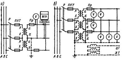
Rice. 46. Connection diagrams for voltage transformers
In normal mode, voltmeters of all phases show phase voltage. When any phase is shorted to ground, voltmeters connected to the other two phases of the VT will show line voltages, and the voltmeter on the closed phase will show zero.
The phase at which the voltage is zero is shorted to ground. An insulation monitoring relay is connected to terminals a1-x1 of the additional windings (see the dashed line in Fig. 46, b), which is activated when any phase of the primary network is shorted to ground and closes the signal circuit.
Voltage transformers are selected according to their rated voltage, number of phases, type of installation, accuracy class and maximum power of the secondary winding. 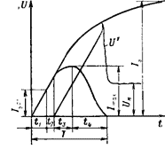
Rice. 47. Short-circuit current rise curves. and changes in current in the circuit when it is turned off by a high-speed switch
High-speed switches are used to turn on and off DC circuits under load and automatically turn them off during overloads and short circuits. They are both switching devices and overcurrent protection.
High-speed circuit breakers (BV) are used for protection against short-circuit currents. on substation feeders, sectioning posts and to protect converters.
Short circuit switch-off time T (Fig. 47) can be divided into four periods. During the 1% time, the current increases to a value equal to the switch setting. This time does not depend on the design of the switch and is determined by the value of the current and the parameters of the short-circuit circuit. Interval h is the switch’s own time (thousandths of a second), during which the current continues to increase until the main contacts of the switch begin to diverge. The U value is determined by the design of the switch. The smaller U is, the better the switch. The U interval characterizes the beginning of the divergence of the switch contacts and the increase in current to the maximum. When an arc occurs between the contacts, the resistance of the short-circuit circuit. increases, and the current, having reached its maximum, will begin to decrease. The value of t3 is also determined by the design of the switch. During time U, the electric arc continues to burn and lengthen between the horns of the arc-extinguishing chamber, and the current sharply decreases and the arc breaks. The ts-U interval is called the arc extinction time. If this time is reduced excessively, large overvoltages may occur during the shutdown process. Reducing the current switched off by the switch and facilitating the switching process are achieved mainly by reducing the tt interval. For a greater limitation of the value, it is necessary to have the shortest possible time interval h-t3.
Overvoltages at the divergent contacts of switches when disconnecting the BV reach 12-15 kV. The total tripping time depends on the design of the circuit breaker, the voltage and inductance of the disconnected circuit. The breaking capacity of BV is not standardized. High-speed switches can be polarized, which operate when a current is in a certain direction, and non-polarized, which operate regardless of the direction of the current, but depending on its value.
The development of a 6.3 kA high-speed circuit breaker is being completed.
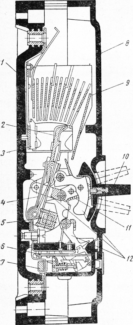
Rice. 48. General view of the high-speed switch AB-2/4:
1 - frame with trolley; 2 - block contacts; 3 - magnetic circuit and switching mechanism; 4 - arc extinguishing chamber; 5 and 7 - buses for connecting BW; 6 - shunt
The AB-2/4 high-speed switch (Fig. 48), polarized, designed for 2 kA and 4 kV, is used as a feeder and cathode. It consists of a magnetic core with a shutdown mechanism 3, an arc-extinguishing chamber 4 and a frame with a trolley 1.
The magnetic core (Fig. 49, a) is a steel bar 7 with a rod 6 and an inverted U-shaped core / attached to it. An armature 4 is hinged on the upper core 5. Screw 2 is used to change the air gap when adjusting the current setting of the circuit breaker. On rod 6 and the U-shaped core there are respectively holding and turning on coils, and on the left rod of core 1 there is a turn of the main current through which the feeder or rectifier current flows. The holding coil is continuously flowed with current from a 110 V battery.
To turn on the BW, voltage is applied to the switching coil. The BV is switched off by breaking the circuit of the holding coil; automatic shutdown occurs during overloads and short circuits. due to a change in the flux in the middle core with increasing current in the demagnetizing coil.
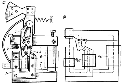
Rice. 49. Magnetic core of switch AB-2/4: o - general view: b - direction of magnetic flux
In the off position, armature 4 (see Fig. 49, a) is attracted to the left rod of core 1 and is held by springs and the force created by the magnetic flux of the holding coil. The magnetic flux of the demagnetizing coil should act in the middle rod opposite to the flux of the holding coil (Fig. 49, b). When the BV is turned on, the direction of the current in the switching coil must be such that the magnetic flux Fvk, which closes through the left rod of core 1 and armature 4, is directed opposite to the flow of the holding coil Fdk. In this case, the force of attraction from the middle rod increases and the anchor is attracted to it, overcoming the tension of the springs. In this case, the flows Fvk and Fdk coincide in direction (see Fig. 49, b). When the turning coil is de-energized, the armature is held in the on position by the force created by the magnetic flux Fdk.
The mechanism for switching on the BV is made with free release, i.e. it ensures automatic shutdown when the BV is switched on. When the BV is turned off, a powerful arc occurs, for which a labyrinth-slit type arc-extinguishing chamber is designed. In the chambers, the arc is stretched to 4.5 m using magnetic blast and cooled. The main current flows through the magnetic blast coils. Inside the chamber there are two arc extinguishing horns, and in its upper part there are flame arresting grilles designed to cool and deionize the arc flame.
High-speed switches are equipped with an inductive shunt 6 (see Fig. 48), consisting of a copper bus 7 with a package of electrical steel plates placed on it. The shunt is connected parallel to the demagnetizing turn of the main current. With short circuit Most of the current flows through the demagnetizing turn, since the inductive reactance of the shunt is many times greater than that of the main current turn. A sharp increase in current in the main turn contributes to the rapid disconnection of the circuit even at relatively low values of short-circuit current.
The AB-2/4 switch belongs to the category of spring-magnetic ones, since it is switched off under the influence of spring tension and magnetic forces. The VAB-28 switch is polarized, used as a cathode to protect the rectifier and in supply lines as a feeder. It has two arc chutes with double circuit breaker. The VAB-43 switch is also polarized.
Busbars and cables at traction substations are designed to connect devices. Busbars are reinforced with insulators, and cables are laid in the ground or on special structures. The buses of closed switchgears are made rigid, and those of open switchgears are flexible. The tire material is copper and aluminum. Copper busbars are used in high-power installations, and aluminum busbars are used in installations of various voltages. In closed installations, rectangular, box-shaped and other cross-section tires are used. For high currents, busbars are installed consisting of several parallel strips connected in a package, with spacers between them equal to the thickness of the strip.
The tires are connected end-to-end by welding, overlapping, using a bolted connection or pressure. Tires are placed in horizontal, vertical or inclined planes, and in relation to one another - flat or on an edge. Rigid busbars are painted; with alternating current, phase A is painted yellow, phase B green, phase C red, zero buses white or purple. With direct current, the positive polarity “plus” bus is painted red, and the negative polarity “minus” bus is blue. Flexible busbars in switchgear are made of stranded aluminum or steel-aluminum wires, and sometimes copper. These tires are not paintable. Busbars are selected according to current, followed by checking rigid busbars for the dynamic and thermal effects of short-circuit currents, and flexible busbars in installations over 110 kV - according to corona conditions and whipping.
Cables are used for power and control (see paragraph 8). The length of the cables at the substation reaches 4-7 km.
Insulators are used to secure busbars and isolate them from grounded parts. Rigid busbars are mounted on support insulators, and flexible busbars are mounted on pin and suspension insulators. When busbars pass through walls and interfloor ceilings, bushing insulators are installed. Support insulators for voltages up to 35 kV are manufactured in five series: A, B, C, D, E. Insulators of each series are divided by voltage and destructive load. The selection of insulators is carried out according to the rated voltage, installation location and loads acting on the insulator during a short circuit.
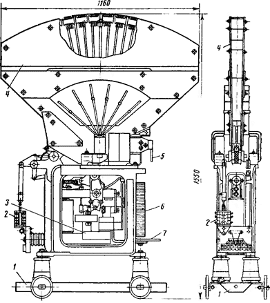
Complete switchgear KRU consists of closed chambers, inside of which equipment is mounted. Switchgear chambers installed against the wall, depending on their purpose, have different filling patterns and can be equipped with oil switches, voltage transformers, arresters, fuses, etc.
Switchgear chambers (figure below) consist of a housing and a withdrawable part - a trolley with equipment. During inspections and repairs, the trolley with equipment is rolled out along special guides into the control corridor.
1 - plug-type disconnector, 2 - power cables,
3 - current transformer, 4 - VMP-10K circuit breaker on a withdrawable trolley,
5 - tires, 6 - switch drive
IN switchgear chambers with oil switches 4 there are plug-type disconnectors, the moving part of which is installed on the trolley, and the fixed part is installed in the cabinet body. To prevent the disconnecting contacts from switching off under load, there is a mechanical lock that prevents the trolley from being rolled out when the switch is on.
The wires of the secondary circuits of the camera body are connected to the wires mounted on the cart using a flexible hose of sufficient length, which has plug-type disconnect contacts that are turned off only when necessary. The welded structure of the switchgear housing is assembled from angle steel, and the housing walls are made of sheet steel 3 mm thick. On the front side, the camera body has instrument compartment doors (at the top) and trolley compartment doors. The walls on the back are removable.
KRU cameras have four compartments separated by metal partitions: busbars, current transformers, switches and instruments. This division into compartments is necessary to comply with safety regulations when work in switchgear chambers, as well as to limit equipment damage when arc short circuits occur in the chamber.
A switch drive is mounted on the front wall of the cart, and a lighting lamp is installed on its inner side. Through three glazed holes on the front wall, the oil indicators of all cylinders of the switch are visible.
The roll-out trolley can occupy three positions: working, control (test) and repair. Working is the position of the trolley in the cabinet body when the circuits of primary and secondary connections are included in the circuit and ensure normal operation of the cabinet.
When the trolley is in the control position in the cabinet body, the primary connection circuits are disconnected by plug disconnectors, and the secondary connection circuits are included in the circuit and ensure the operation of the switch with the drive. The repair position is when the trolley is located outside the cabinet body and all plug contacts are open.
When rolling out the trolley to the repair position, the holes in switchgear chamber partition for the entry and exit of the disconnecting contacts are automatically closed with metal curtains, which must have lugs for locks that are locked during repair work on the trolleys.
Switchgears assembled from switchgear chambers have test carts without front walls, on which only disconnecting contacts are mounted (without oil switching). Such carts are necessary for phasing cables, as well as for preventive testing of cable lines connected to switchgear chambers.
Currently, except switchgear cameras, intended for indoor installations, cameras for outdoor installations (KRUN) with voltages up to 10 kV are widely used, having two versions: with roll-out carts and without carts.
Metal KRUN frame assembled from angle steel, on the front side of which there are steel doors. The remaining sides, as well as the ceiling and floor of the chamber with equipment and tires, are covered with solid steel sheets.
Page 1 of 2
1. SWITCH DEVICES LOW VOLTAGE
1.1. Fuses
1.1.1. General information
Fuse- an electrical device designed to protect electrical circuits in abnormal operating modes: thermal overloads and short circuits (short circuit). It is connected in series to the circuit of the protected object (device, equipment, etc.). The main element of the fuse is fuse link(copper, aluminum, zinc, silver-plated copper) from a flat plate with narrow isthmuses or from round metal wire, which melts under abnormal operating conditions. The fuse link should not burn out at a current equal to 120-130% of the rated current for an hour. At a current of 200% of 1nom it should operate within an hour. Fuses must meet the following requirements: 1. The ampersecond (protective) characteristic of the fuse must be lower, but as close as possible to the ampersecond characteristic of the protected object, Fig. 1.1.
Rice. 1.1. : 1 - fuse, 2 - protected object
2. The response time of the fuse during a short circuit should be as short as possible , especially when protecting semiconductor devices. 3. In the event of a short circuit in the protected circuit, the fuses must provide selectivity of protection (see below). 4. The characteristics of the fuses must be stable. 5. Due to the increased power of electrical installations, fuses must have a high breaking capacity. 6. The design of the fuse should be simple and convenient when replacing the fuse link when it burns out. Silver fuse links form oxide films that conduct electric current, i.e. do not change their characteristics. Recently, fuse links have been widely used made of copper, covered with a thin layer of silver. Several levels of protection are usually installed between the power source and the consumer, Fig. 1.2. The RSh fuse, which passes a higher rated current, has an insert with a larger cross-section than the RC2 fuse, installed directly at the consumer. In the event of a short circuit, it is necessary that the power is turned off by a fuse located at the location of the fault. The remaining consumers must not lose power, that is, all other fuses must remain operational. This coordination of fuses is called selectivity or selectivity. In Fig. 1.3 shows an electrical circuit for fuse protection of short-circuited asynchronous motors powered from the general distribution board of the distribution board.
Rice. 1.2. Selective defense
1.1.2. Designs of low voltage fuses Based on the method of extinguishing the arc, low voltage fuses are divided into two groups: fuses without filler and fuses With filler Fuses without filler. PR-2- collapsible fuse. These fuses are available in rated currents from 6 to 1000 A and rated voltages up to 500 V. They are used in both direct and alternating current installations. The fuse housing is a sealed round cartridge made of gas-generating material (fiber), Fig. 1.4.a). It consists of a cylinder 3, a brass holder 4 and a brass cap 5. Fuse link 1 is stamped from zinc and has one or more constrictions ( depending on rated voltage), fig. 1.4.c). With the appropriate current, the fuse-link melts at the narrowing point and an electric arc occurs. Under the influence of the high temperature of the arc, the walls of the cartridge emit gases (hydrogen, carbon dioxide). The pressure in the cartridge rises to 4-8 MPa in fractions of a half-cycle. Under the influence of a high-pressure gas environment, the arc quickly goes out. Fuse link 1 is pressed against the brass holder 4 by cap 5, which is the output contact, Fig. 1.4.a). In fuses for currents greater than 60 A, fuse link 1 is connected to contact blades 2, Fig. 1.4.6).
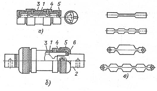
Rice. 1.4.
PR-2 fuses are single-pole, front and rear connections. They operate silently, with virtually no emission of flame or gases. This allows adjacent poles to be mounted at close distances. Compared to some other types of fuses, they have one significant advantage- allow you to quickly replace a burnt-out fuse-link. Fuse PR-2 has a current-limiting effect. In a circuit with a short-circuit current of 50,000 A, a fuse-link with a rated current of 6 A burns out at a current of only 400 A, but with a rated current of 600 A, there is no current limitation and the arc burns throughout the entire half-cycle. A PR-2 fuse is presented in the laboratory. Fuses with fine-grained filler. These fuses are more advanced than non-filler fuses. PN-2- fuse with filler. Square body 1, fig. 1.5, is made of durable porcelain or steatite. Inside the body there are strip fuse links 2 and a filler - quartz sand 3. The fuse links are welded to disk 4, which is attached to plates 5 connected to blade contacts 9.
Rice. 1.5.
The filler used is quartz sand containing SiO2 not less than 98%, with grains of size (0.2-0.4) * 10"4 m and humidity not higher than 3%. Therefore, before backfilling, the sand is thoroughly sifted and dried at a temperature of 120-180 C. Quartz sand grains have high thermal conductivity , thereby intensively removing heat from the arc, facilitating its rapid extinguishing. The fuse-link is made of copper tape with a thickness of 0.1-0.2 mm. To obtain a current-limiting effect, the insert has narrowings 8. The fuse-link is divided into several calibrated parallel branches (up to 9). ) for more complete use of the filler in order to transfer heat to the environment and to reduce the rate of current decay in order to reduce overvoltage at the moment of arc extinguishing. To reduce the melting temperature, tin balls 7 are applied to the inserts (the metallurgical effect is ensured in a few milliseconds). After the fuse trips, the fuse links together with disk 4 are replaced, after which the cartridge is filled with clean and dry sand. To ensure tightness, an asbestos gasket 6 is used. PN-2 fuses are made for rated currents up to 630 A. The maximum switched current reaches 50 kA. Advantages of the fuse-small dimensions, low consumption of scarce materials, high current-limiting ability. The fuse is available in the laboratory. NPN-2 - non-separable fuse, with filler. Has a round glass body. A fuse link is a thin copper plate with constrictions and a metallurgical effect. Clean and dry sand is used as filler. After the fuse link burns out, the fuse must be completely replaced. Available for alternating rated currents up to 60 A at rated voltages up to 500 V. The fuse is available in the laboratory. PRS- threaded fuse, used in small-sized switchgears. Fuse link completed in the form of several parallel wires from copper coated with a thin layer of silver. Placed in a porcelain cartridge filled with quartz sand. The fuse has a trip indicator. When the fuse link burns out, a special spring is released, which throws the peephole into the glazed hole in the fuse housing. After the fuse has tripped, the cartridge with the burnt-out fuse-link and eye is replaced. Fuses are available for currents up to 100 A, voltages up to 440 V DC and up to 500 V AC with a frequency of 50 Hz. Maximum switchable current 60 kA. The fuse is available in the laboratory. PP- 57 - fuse, series 57, fast-acting. The fuse link is made in the form of two silver-plated copper plates with a large ratio between the narrow and wide parts, Fig. 1.6.a).
Electrical apparatus of switchgears
TO category:
Mobile power stations
Electrical apparatus of switchgears
Switching on and off, as well as protecting the equipment of the mobile station, is carried out using electrical devices installed in switchgears.
According to the purpose and type of functions performed, electrical devices of station switchgears can be divided into two main groups - switching devices and protective devices.
Switching devices include devices that are used to switch on and off all or part of an electrical installation, as well as change the primary circuit of the switchgear; Protective devices include devices that protect equipment from overloads and short circuit currents.
The switching devices of switchgears with voltages of 230 and 400 V in mobile stations are switches, batch switches and automatic installation machines.
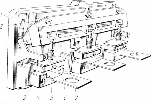
The switch is a three-pole device of a closed design (Fig. 1, a), installed on the Panel panel, or an open design (Fig. 1, b), installed behind the switchboard and controlled by a remote rod using a handle mounted on the front side of the control panel panel. A three-pole switch consists of movable knives and fixed contacts mounted on a panel, which is made of insulating materials (slate, asbestos slate, getinax, etc.). The movable contact knives in the lower part are hinged in the contact posts, and in the upper part they are connected by a common traverse made of insulating material.
Rice. 1. Three-pole switches: a - closed version for 100 a, b - open version for 400 a with remote control; 1 - control handle, 2 - fixed contact, 3 - knife, 4 - shield, 5 - casing, 6 - brackets (internal and external), 7 - rod
When the electrical circuit breaks between the switch knives and the jaws of the fixed contacts, an electric shock occurs, releasing a large amount of heat that destroys the contact surfaces of the knives and jaws. The greater the current in the circuit broken by the switch, the larger the arc. Therefore, to protect the contacts from destruction by the arc, the knives of powerful switches are equipped with spark-extinguishing contacts.
The switches installed on the control panel are covered with a metal casing, upholstered on the inside with sheet asbestos 1-2 mm thick. Open type switches with remote control are equipped with a metal rod connected to a drive installed on the panel, with the help of which the switch is controlled.
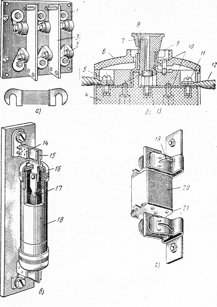
Rice. 2. Package switch: 1 - handle, 2 - axis, 3 - tightening screw, 4 - contact terminal, 5 - mounting strip, c - package (pole), 7 - cover, 8 - contacts, 9 - spring
In switchgears of low-power mobile stations (up to 30 kVA), batch switches are used as disconnecting devices.
The PC packet switch (Fig. 2) consists of movable contacts mounted on an axis with a spring and placed inside carbolite bags with fixed contacts mounted in them. A handle is attached to the end of the switch axis coming out of the bags; when turned, the spring is tensioned. Under the action of a charged spring, the axis rotates and closes or opens the switch contacts at high speed. To quickly extinguish the arc, the package switch contains fiber washers, which, when exposed to high arc temperatures, decompose, releasing gases that promote rupture and extinguishing the arc.
Switchgears of mobile stations use two-pole or three-pole switches.
Switches and batch switches are manual non-automatic devices, for operating which
In necessary cases, direct intervention by operators is required. For automatic opening of electrical circuits during operational switching, as well as during overloads
and short circuits in switchgears of stations, special automatic devices are used, in particular series A machines.
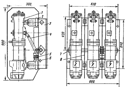
The automatic installation machine A-3100 (Fig. 3) consists of a contact system, an arc extinguishing device and a control mechanism, mounted in a common plastic housing with a lid. The moving contacts are mounted on contact holders connected to copper output busbars using a package of cold-rolled copper sheets 12 mm wide and 0.2 mm thick. The fixed contacts are soldered to copper bars laid on the bottom of the base and equipped with clamps for connection to the line.
To protect against the destructive effects of the arc, the working surfaces of the contacts are covered with metal-ceramic linings. The use of metal-ceramic overlays greatly increases the service life of the contacts, and, consequently, the time between repairs of the machine.
The moving and fixed contacts of each pole of the machine are separated by plastic partitions and enclosed in removable arc-extinguishing chambers 9. Each chamber consists of several steel plates fixed to a fiber frame so that narrow gaps are formed between them, diverging upward. When the machine is turned off, the arc formed at its contacts, thanks to the magnetic field created by the arc current, is drawn into the spaces between the plates of the arc extinguishing devices (grids), splits into a number of small arcs and, intensively cooling on the surface of the plates, is quickly extinguished. The machines are manufactured with manual control.
Rice. 3. Automatic machine A-3100: 1 - base, 2 - moving contact, 3 - fixed contact, 4 - flexible connection, 5 - insulated steel roller, 6 and 7 - releases, 8 - machine cover, 9 - arc extinguishing chamber, 10 - control handle, 11 - spring, 12 - control mechanism levers
The movable contact holders are connected to a common steel insulated roller 5 and through a spring mechanism using levers to a handle. The control mechanism of the machine ensures closing and opening of contacts at a constant speed, independent of the speed of movement of the handle, as well as the necessary pressure on the contacts and automatic shutdown in case of overloads and short circuits.
The position of the control handle determines whether the machine is on or off. If the handle is in the upper position, the machine is turned on, if in the middle (intermediate) and lower position, it is turned off. Moreover, the handle occupies the middle position if the shutdown occurs automatically. To restore the on position of the device after automatic shutdown, it is necessary to lower the handle to the lower position (to the “off” position), engage the levers of the mechanism, and then raise the handle to the uppermost position.
Automatic shutdown of the A-3100 device is performed by a special device - a release built into a separate plastic case and installed under the cover of the machine.
Releases can be only with a thermal element or only with an electromagnetic element, as well as combined. The combined release (Fig. 4) consists of thermal and electromagnetic elements installed in each pole of the machine. The thermal element serves to protect the electrical installation from overload currents, and the electromagnetic element - from short circuit currents.
The thermal element consists of a bimetallic plate, which, under the influence of the current passing through it, heats up, bends and turns the tripping rack of the control mechanism, resulting in an automatic shutdown. In this case, the machine will turn off regardless of whether an overload occurs in one or more phases. The machine reacts to an overload of more than 35% of the rated current.
The greater the overload current, the faster the thermal element will operate and the machine will turn off. So, with an overload of about 40%, the machine will turn off within 50-55 minutes, and with an overload of 80-100% - within 30-90 seconds.
The electromagnetic element consists of an armature held by a return spring and a magnetic core, inside of which the operating current bus is located. When the rated current flows through the bus, the magnetic field created in the magnetic core is so insignificant that it cannot overcome the opposing force of the spring, and the armature maintains a free position.
Rice. 4. Combined splitter of the A-3100 machine: 1 - base, 2 - bimetallic plate, 3 - magnetic circuit, 4 - tripping rail, 5 - return spring, 6 - armature, 7 - current-carrying busbar
At the moment a short circuit occurs between the phases, the armature of the electromagnetic element corresponding to a given pole, retracting (under the influence of a strong magnetic field caused by the short circuit current), acts on the rail common to all poles and, turning it, turns off all three poles of the machine. The main parts of the distributor are mounted on a plastic base.
A-3100 automatic machines are produced with rated currents from 50 to 600 A. They can be without releases, with one or two separators. Automatic machines without trip units serve as ordinary switching devices. If there are releases, the rated current of the circuit breaker is determined by the rated current of the setting of the splitter, adjusted by the input.
Other machines are also used in switchgear of mobile stations (AP-50, AP-2020, etc.). They work the same way as A-3100 automatic machines, and differ from the latter in design, size and rated current.
Automatic machines combine, to a certain extent, the functions of a switch and a fuse, since, being switching devices, they simultaneously serve as protective devices. They are used in switchgear of power plants with a power of over 50 kVA (PES -60, PES -100, DES -200 and DR-) - In low-power power plants, the protection of individual parts and the entire installation is carried out using structurally simple and fairly reliable devices - fuses.
A fuse is an electrical device in which, at a certain strength of current flowing through it, the fuse-link melts (burns out), and thus opens the electrical circuit, due to which the electrical equipment in the area protected by the fuse is protected from the effects of dangerous overload or short-circuit currents. The operation of the fuse is based on the thermal effect of electric current.
The disconnecting element of the fuse is its fuse link, consisting of a metal wire or thin strip. Fuse links are made of lead, zinc or copper, as well as alloys of these metals. The most widely used fusible links are made of copper.
Fuses are characterized by rated voltage and rated current.
The rated voltage of the fuse corresponds to the highest rated voltage of the circuits in which the use of this fuse is permitted. Thus, fuses marked 500 V can be used in circuits with voltages of 500 V and below.
The rated current of a fuse-link is the highest current that the fuse-link can withstand for an indefinitely long time.
But the minimum current of a fuse is the long-term current for which the fuse is designed (cartridge, contact blades, and stands). The holder indicates the rated current corresponding to the highest rated current of the fuse links intended for this fuse. Thus, in a fuse holder with a rated current of 600 A, a fuse link with a rated current of no higher than 600 A can be installed.
In the switchgear of stations, open plate fuses are used, and more recently - mainly closed plug or tubular fuses.
The plate fuse (Fig. 5, a) is a shield made of insulating material with brass cams mounted on it, equipped with clamping bolts for attaching fuse links. The cams and fuse-link of each phase are separated by a fire-resistant partition, which prevents arc transfer to adjacent phases when the insert burns out. The fuse link consists of several tinned copper wires soldered to brass plates (tips) with cutouts for attaching the insert to the cams.
Rice. 5. Fuses: a - open plate, b-plug, c closed without filler, d - closed with filler; 1 - shield, 2 cam, 3 - fire-resistant partition, 4 - block, 5 and 11 - linear contacts, 6 - cover, 7 - plug, 8 and 17 - fusible links, 9 - threaded sleeve, 10 - contact plates, 12 - power line wire, 13 - contact screw, 14 - contact stand, 15 - contact knife, 16 - brass cap, 18 - fiber tube, 19 - spring ring, 20 - porcelain cartridge body, 21 - cartridge cover
The fuse panel is covered with a casing made of fire-resistant material to protect personnel when the fuse link burns out from particles of molten metal, as well as to prevent fire.
Plate fuses were manufactured for currents up to 200 A and were widely used in switchgear of mobile stations produced before 1956, which, however, are still in use in large numbers today. The blade fuse has a number of significant disadvantages. The main ones are the danger of accidental contact with live parts of the fuse, and the possibility of burns to personnel by drops of molten metal when the fuse link burns out.
The plug fuse (Fig. 5, b) consists of a porcelain block with contacts and a threaded plug with a fuse insert enclosed in it.
The block is closed with a lid. The current passes through the linear contact of the network to the contact screw, and then through the fuse-link and sleeve to the linear contact and then into the consumer line.
Plug fuses with a Ts-27 thread are designed for a current of 6-25 a, and with a Ts-33 thread - for 10-60 a. Fuses with Ts-27 threads are used mainly to protect lighting networks. To protect power circuits, plug fuses with Ts-33 threads are used.
The PR fuse (Fig. 5, c) consists of an insulating base with contact posts and a fiber tube with contact blades. The contact knives are secured at the ends of the fiber tube with brass caps. A fusible insert made in the form of a plate with narrowing areas is bolted to the internal parts of the knives.
The material for the manufacture of fuse links is a zinc alloy with a melting point of about 420°C. When the current in the electrical circuit protected by the fuse increases beyond the nominal value, the fuse-link burns out simultaneously in all narrowed places and breaks the electrical circuit. The resulting arc quickly goes out under the influence of high pressure gases. High-pressure gases (up to 100 kg/cm2) are formed in the fiber tube of the cartridge due to the decomposition of the fiber when its walls are exposed to high arc temperatures.
PR fuse holders do not have a filler; their fusible inserts are surrounded by air, which increases the duration of the arc process when the insert burns out and therefore worsens the characteristics of the fuse and also reduces its service life.
A more advanced fuse is a closed fuse PN with a filler.
The PN fuse (Fig. 5, d) consists of contact posts and a cartridge filled with quartz sand with contact knives. The cartridge is a porcelain body with a cylindrical hole, closed at the ends with metal covers 21 carrying contact knives. A fusible insert is welded to the internal parts of the contact knives (by spot welding).
The fuse link consists of one, two or three stamped copper strips with a thickness of 0.15-0.2 mm. In some PN fuses (for example, in PN-2 fuses produced by the Kursk Electrical Apparatus Plant), the fuse link is made of two or three strips of the same size, but of different thicknesses, which significantly improves the performance of the fuse.
To improve the characteristics of the PN fuse, a tin ball is fused in the center of each strip (in the isthmus between the stamped holes) of the insert. The tin ball is designed to reduce the melting point of fuse elements. When the fuse link is heated to the melting temperature of tin, the ball melts and its molecules, penetrating into the copper, form an alloy, the melting point of which is much lower than the melting point of copper. The fuse holder is filled with clean, dry (humidity no more than 0.05%) quartz sand containing at least 99% quartz (the size of quartz grains should be about 0.5 mm).
The PN cartridge covers have T-shaped protrusions that serve to install the cartridge in the contact posts and remove them from them using a special removable handle, the cutouts of which correspond to the protrusions of the covers. The contact posts are copper plates equipped with spring rings 19, which ensure reliable contact of the cartridge knives with the jaws of the contact posts.
PN cartridges are produced for rated currents of 100; 250; 400; 600 and 1000 A with fuse links for 25 A and higher.
In switchgear of mobile stations, fuses of other designs are used, but they differ little from the fuses described above.
Fuse links are available for the following rated currents: 4; 6; 10; 15; 20; 25; 35; 45; 60; 80; 100; 125; 160; 200; 250; 300; 350; 400 and 600 a.
With a rated current of, for example, 50 A, the fuse link should be selected for a rated current of 60 A.
2. The rated current of the fuse-link /n.v must be equal to the starting current /p, reduced by 2.5 times for the protected section of the line, if one short-circuited electric motor is connected to it, or be slightly higher.
3. When choosing fuse links installed in series in a line, each subsequent fuse link, counting from the generator of a mobile station or from a power transformer, must be selected one step lower in the rated current of standard fuse links. So, when installing a 100 fuse in the fuse closest to the generator, the following fuses should have 80 fuse; 60; 45 a and below. Compliance with this condition1 is necessary to ensure the so-called selective action of the fuses. Selectivity refers to the action of fuses during a short circuit (short circuit), when the fuse link closest to the short circuit burns out first, and only the section of the network protected by this fuse is switched off.
TO category: - Mobile power stations